1 internal access, 2 mode dip switch settings, 3 level display calibration – RTS SSA-424 User Manual
Page 16: 4appendix
16 SSA-424 U
SER
M
ANUAL
4
Appendix
4.1
I
NTERNAL
A
CCESS
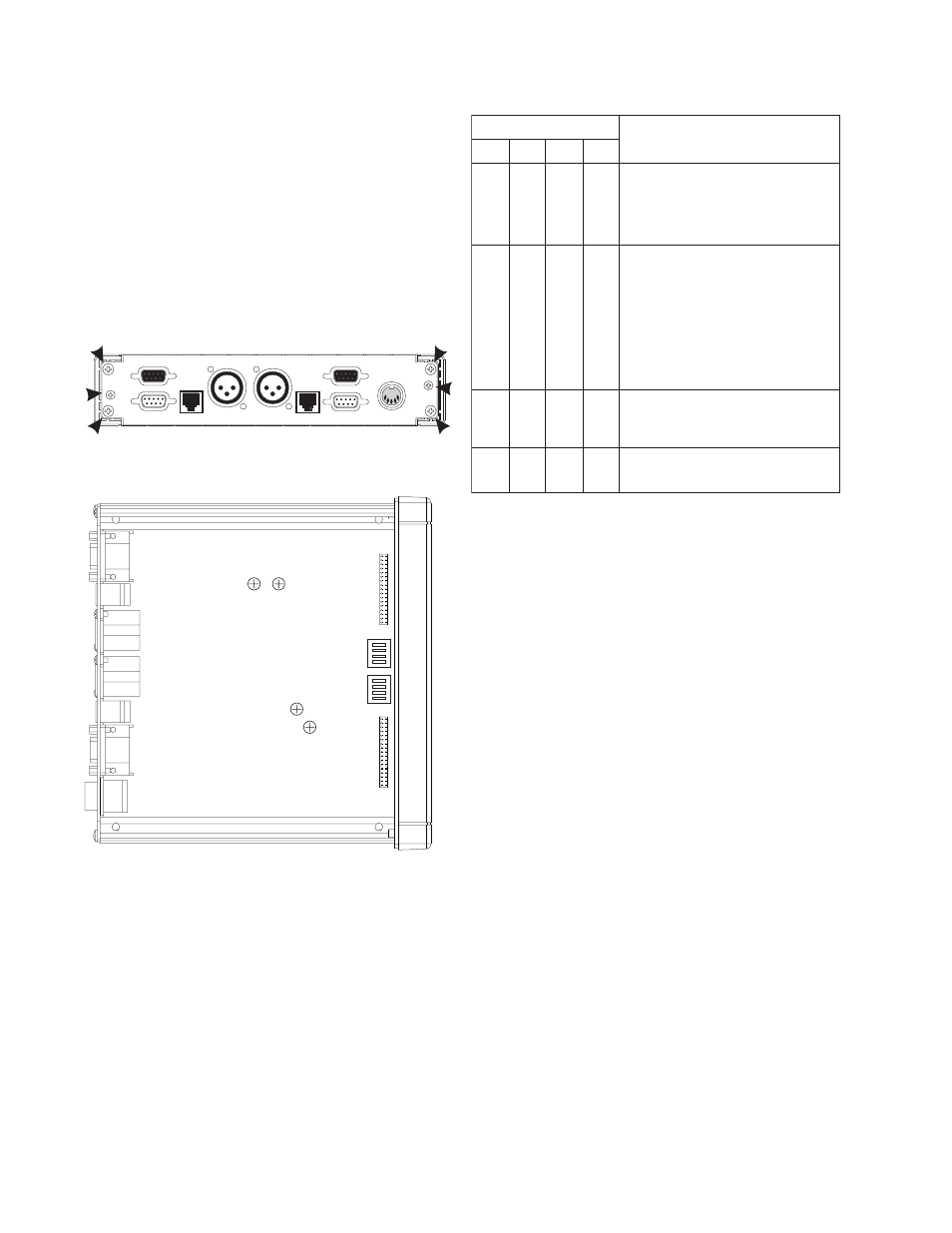
1 Remove six screws from the back cover.
2 Remove the top cover.
This provides access to all internal adjustments.
3 For option card installation, slide the circuit board
out toward the back to remove it from the bottom
cover.
AUX
J4B
J3B
J2B
J1B
J1A
J2A
J3A
J4A
AUX
4 WIRE SYSTEM
4 WIRE SYSTEM
2 WIRE SYSTEM
Telex Communications, Inc., Made in U.S.A.
RTN
+5V
RTN
+15V
-15V
-15V 0.3A
+15V 1.6A
+5V 3A
J5 POWER
Figure 9. Location of screws for disassembly.
RV102
RV101
RV202
RV201
S301
S302
Figure 10. Locations of internal controls.
4.2
M
ODE
D
IP
S
WITCH
S
ETTINGS
S301 controls the operating mode for System B and
S302 controls the operating mode for System A.
Settings are summarized in Table 4
Table 4. Mode DIP Switch Settings
s
g
n
i
t
t
e
S
h
c
t
i
w
S
s
g
n
i
t
t
e
S
h
c
t
i
w
S
s
g
n
i
t
t
e
S
h
c
t
i
w
S
s
g
n
i
t
t
e
S
h
c
t
i
w
S
s
g
n
i
t
t
e
S
h
c
t
i
w
S
n
o
i
t
p
i
r
c
s
e
D
n
o
i
t
p
i
r
c
s
e
D
n
o
i
t
p
i
r
c
s
e
D
n
o
i
t
p
i
r
c
s
e
D
n
o
i
t
p
i
r
c
s
e
D
1
1
1
1
1
2
2
2
2
2
3
3
3
3
3
4
4
4
4
4
f
f
O
f
f
O
f
f
O
f
f
O
e
d
o
M
x
e
l
p
u
D
ll
u
F
/
f
l
a
H
,
1
n
o
i
t
a
r
u
g
i
f
n
o
C
:
)
t
l
u
a
f
e
d
(
.
s
e
d
o
m
n
e
e
w
t
e
b
s
e
h
c
t
i
w
s
y
ll
a
c
i
t
a
m
o
t
u
A
h
g
i
h
s
i
e
r
e
h
t
e
r
e
h
w
s
n
o
i
t
a
u
t
i
s
n
i
l
u
f
e
s
U
s
i
e
r
e
h
t
n
e
h
w
l
u
f
e
s
u
o
s
l
A
.
e
s
i
o
n
t
n
e
i
b
m
a
.
k
c
a
b
d
e
e
f
c
i
t
s
u
o
c
a
n
O
f
f
O
f
f
O
f
f
O
:
e
d
o
M
x
e
l
p
u
D
ll
u
F
d
e
h
c
t
i
w
S
,
2
n
o
i
t
a
r
u
g
i
f
n
o
C
9
-
3
x
e
l
p
u
d
ll
u
f
o
t
x
e
l
p
u
d
f
l
a
h
m
o
r
f
s
e
h
c
t
i
w
S
-
4
e
h
t
n
o
s
n
i
g
e
b
n
o
i
t
a
s
r
e
v
n
o
c
r
e
t
f
a
s
d
n
o
c
e
s
-
0
6
li
t
n
u
e
d
o
m
x
e
l
p
u
d
ll
u
f
n
i
s
y
a
t
S
.
e
n
il
e
r
i
w
s
i
h
T
.
s
e
s
a
e
c
n
o
i
t
a
s
r
e
v
n
o
c
r
e
t
f
a
s
d
n
o
c
e
s
0
9
f
o
s
d
o
i
d
r
e
p
g
n
i
r
u
d
t
e
i
u
q
e
n
il
e
h
t
p
e
e
k
o
t
s
p
l
e
h
l
a
r
u
t
a
n
g
n
i
t
t
i
m
r
e
p
e
li
h
w
,
n
o
i
t
a
s
r
e
v
n
o
c
o
n
s
i
s
i
h
T
.
g
n
i
k
l
a
t
e
r
a
e
l
p
o
e
p
n
e
h
w
n
o
i
t
a
s
r
e
v
n
o
c
y
n
a
m
r
o
f
e
d
o
m
g
n
i
t
a
r
e
p
o
d
e
r
r
e
f
e
r
p
e
h
t
-
e
s
o
l
c
,
t
s
a
f
r
o
f
y
l
r
a
l
u
c
i
t
r
a
p
d
n
a
,
s
n
o
i
t
a
u
t
i
s
.
s
n
o
i
t
a
r
e
p
o
m
a
e
t
,
n
o
i
t
a
n
i
d
r
o
o
c
n
O
f
f
O
f
f
O
n
O
:
e
d
o
M
x
e
l
p
u
D
ll
u
F
d
e
k
c
o
L
,
3
n
o
i
t
a
r
u
g
i
f
n
o
C
d
i
r
b
y
h
a
e
c
n
o
t
u
b
,
2
n
o
i
t
a
r
u
g
i
f
n
o
c
s
a
e
m
a
S
e
d
o
m
t
a
h
t
n
i
s
y
a
t
s
t
i
,
e
d
o
m
x
e
l
p
u
d
-
ll
u
f
s
r
e
t
n
e
.
n
w
o
d
-
r
e
w
o
p
li
t
n
u
f
f
O
f
f
O
n
O
f
f
O
:
e
d
o
M
x
e
l
p
u
D
ll
u
F
/
f
l
a
H
,
4
n
o
i
t
a
r
u
g
i
f
n
o
C
r
e
h
g
i
h
h
t
i
w
t
u
b
,
1
n
o
i
t
a
r
u
g
i
f
n
o
c
o
t
r
a
li
m
i
S
.
y
t
i
v
i
t
i
s
n
e
s
Half-duplex Definition: Only one side of the line
can talk at a time and the other side must wait until
the first side is done talking before responding.
Full-duplex Definition: Both sides of the line can
talk simultaneously.
4.3
L
EVEL
D
ISPLAY
C
ALIBRATION
✏
This is a factory preset adjustment and
should not require readjustment.
1 On the front panel, set the 4W LEVEL REF SEL
controls to -10dB.
2 Set the 2W CHAN SEL switches to 1.
3 Input a 1kHz, -10dBu test signal at J1A (System
A) or J1B (System B). (Pin 1, signal common;
pin 2, signal high.)
4 Adjust RV101 (System A) or RV201 (System B)
while watching the top display (TO4W). All of the
green displays should be lit and no amber
displays should be lit.
5 Remove the test signal.