Pin arrangement, Absolute maximum ratings – Renesas RD74LVC04B User Manual
Page 2
RD74LVC04B
Rev.1.00, Apr.08.2004, page 2 of 7
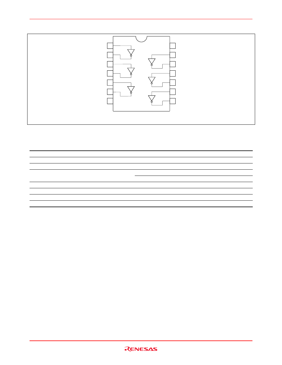
Pin Arrangement
(Top view)
11
12
13
14 V
CC
6A
6Y
5A
5Y
4A
1
2
3
4
5
6
7
8
9
10
1A
GND
4Y
1Y
2A
2Y
3A
3Y
Absolute Maximum Ratings
Item
Symbol
Ratings
Unit
Conditions
Supply voltage range
V
CC
–0.5 to 7.0
V
Input diode current
I
IK
–50
mA
V
I
= –0.5 V
Input voltage
V
I
–0.5 to 7.0
V
–50
mA
V
O
= –0.5 V
Output diode current
I
OK
50
mA
V
O
= V
CC
+0.5 V
Output voltage
V
O
–0.5 to V
CC
+0.5
V
Output current
I
O
±50
mA
V
CC
, GND current / pin
I
CC
or I
GND
100
mA
Storage temperature
Tstg
–65 to +150
°C
Note:
The absolute maximum ratings are values, which must not individually be exceeded, and furthermore, no two of
which may be realized at the same time.