Connection procedure (see figure 3), External dimensions and a sample foot pattern – Renesas R0E530650CFJ30 User Manual
Page 2
R0E530650CFJ30 User’s
Manual
5. Connection Procedure
(See Figure 3)
REJ10J1902-0200 Rev.2.00
Page 2 of 4
Apr 16, 2010
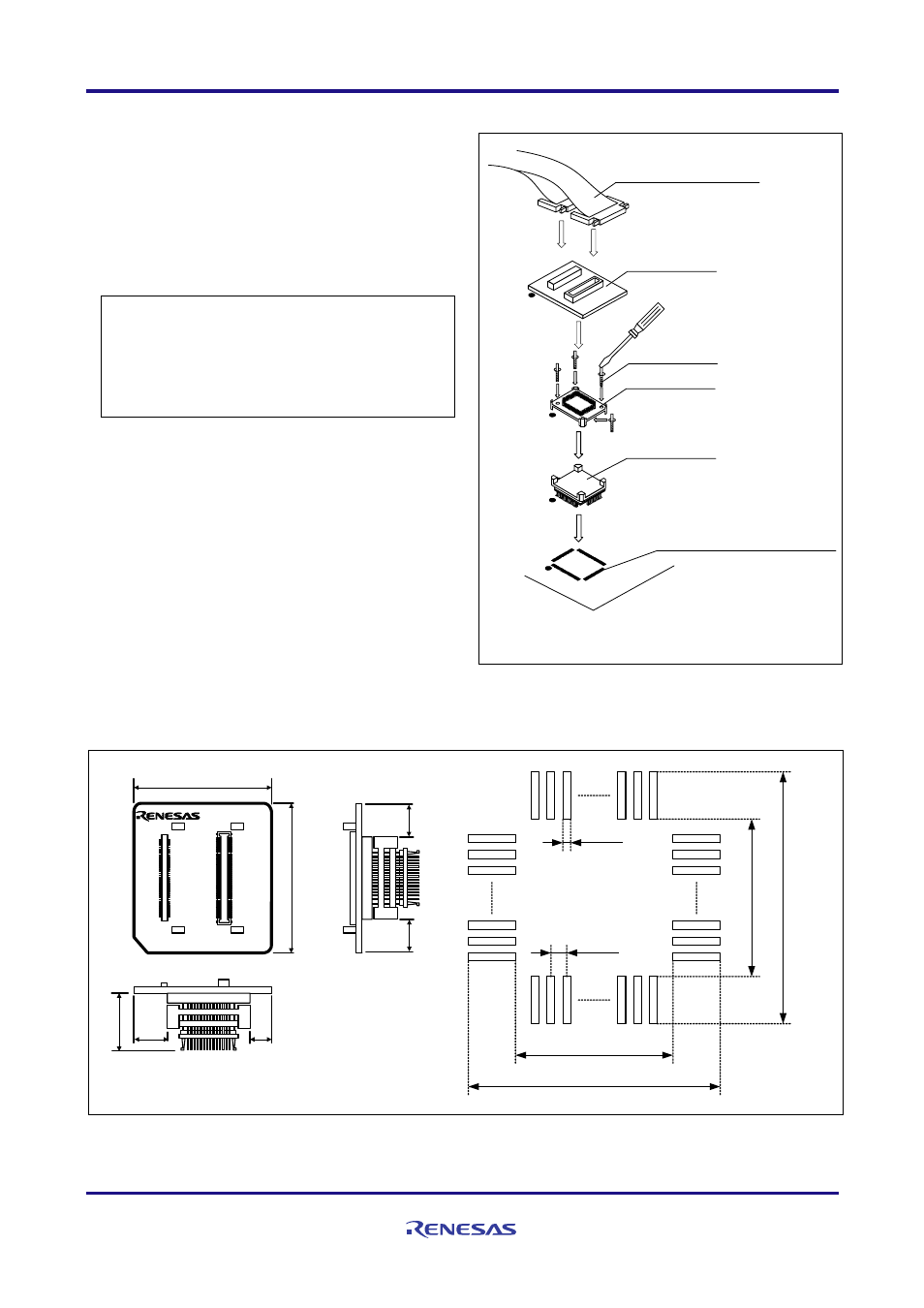
The procedure for connecting the R0E530650CFJ30 is shown
below.
(1) Mount the NQPACK080SB on the user system.
(2) Attach the YQPACK080SB on the NQPACK080SB.
(3) Secure the four corners of the YQPACK080SB with the
YQ-GUIDEs.
● Do NOT use the screws included with the
YQPACK080SB for fixing the YQPACK080SB.
● Do NOT use the screwdriver included with the
NQPACK080SB for fixing the YQ-GUIDEs. That is
used only for the HQPACK080SB.
(4) Mount the R0E530650CFJ30 on the YQPACK080SB.
(5) Attach the flexible cable R0E001000FLX10 of the
emulator to the R0E530650CFJ30.
80-pin 0.65mm pitch
(PLQP0080JA-A) foot pattern
YQPACK080SB
NQPACK080SB
YQ-GUIDE(×4)
R0E530650CFJ30
●:No.1 pin
Be sure to align the pins.
(1)
(2)
(3)
(4)
(5)
Use a slotted screwdriver.
Flexible cable
R0E001000FLX10
Figure 3 Connection procedure of the R0E530650CFJ30
6. External Dimensions and a Sample Foot Pattern
38.00
35.00
16
.50
R0E530650CFJ30
REV.A
CN1
1
50
51
100
CN2
1
50
51
100
MADE IN JAPAN
13
.4
0
17
.2
0
13.40
17.20
0.65
0.35
Unit : mm
6.83
4.08
6.
95
6.95
Figure 4 External dimensions and a sample foot pattern of the R0E530650CFJ30