Chapter 4. board layout, Component layout, Chapt – Renesas H8SX/1668R User Manual
Page 8: Er 4. board layout
Chapt
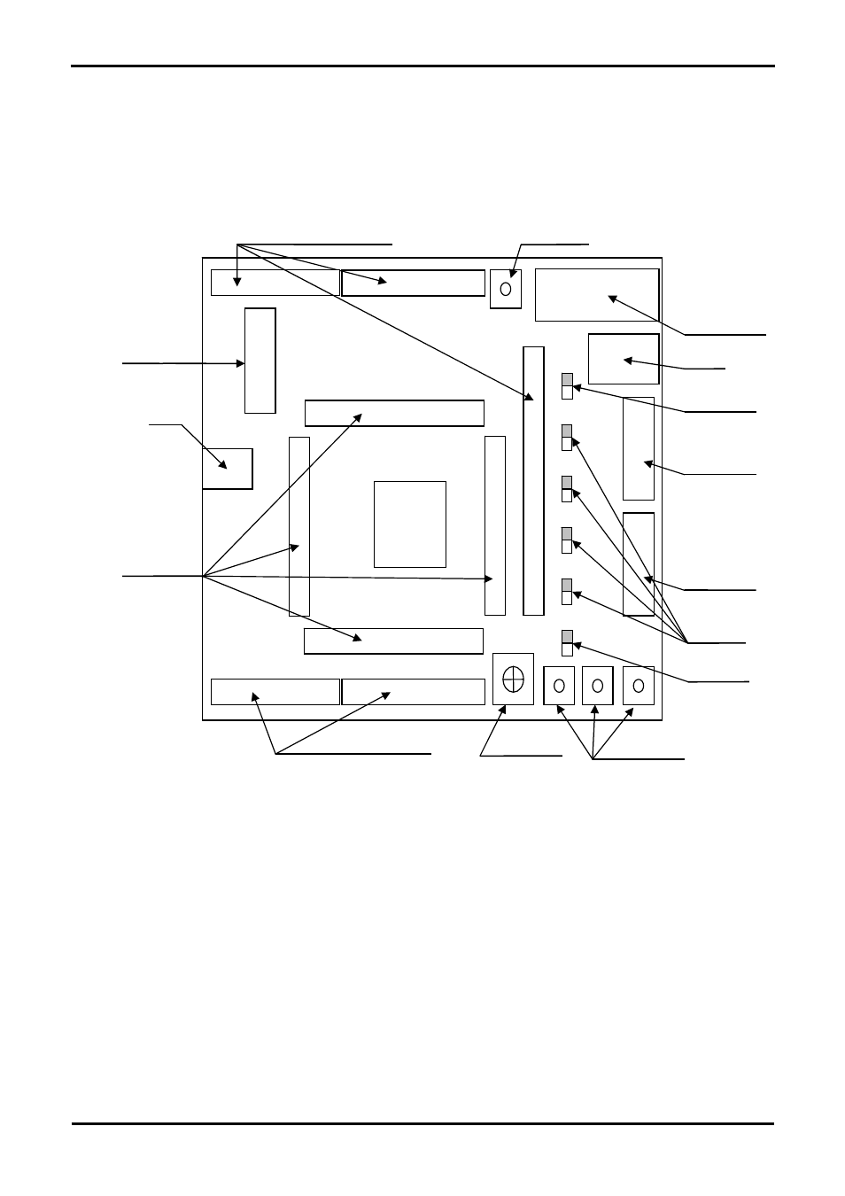
Figure 4-1: Board Layout
er 4. Board Layout
4.1. Component Layout
The following diagram shows top layer component layout of the board.
User switches
E8 Header
Power
RS232 Serial
Application board interfaces
LCD Display
Microcontroller
pin headers
Application board interface
Potentiometer
User LEDs
Reset switch
JA1
J1
J2
J4
LCD
Power LED
MCU
JA5
E10A Header
JA2
JA6
JA3
Boot LED
USB
J3
6