Parameter measurement information – National DS36C278 User Manual
Page 5
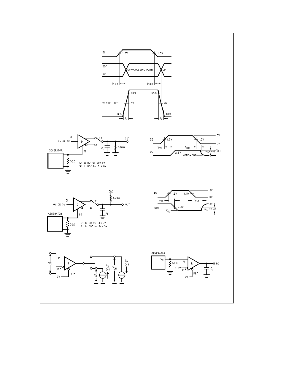
Parameter Measurement Information
(Continued)
TL F 12040 – 6
FIGURE 6 Driver Differential Propagation Delays and Differential Rise and Fall Times
TL F 12040 – 7
FIGURE 7 TRI-STATE Test Circuit (t
PZH
t
PHZ
)
TL F 12040 – 8
FIGURE 8 TRI-STATE Waveforms (t
PZH
t
PHZ
)
TL F 12040 – 9
FIGURE 9 TRI-STATE Test Circuit (t
PZL
t
PLZ
)
TL F 12040 – 10
FIGURE 10 TRI-STATE Waveforms (t
PZL
t
PLZ
)
TL F 12040 – 11
FIGURE 11 Receiver V
OH
and V
OL
TL F 12040 – 12
FIGURE 12 Receiver Differential Propagation Delay
Test Circuit
http
www national com
5