Burner base removal, Blower replacement – Napoleon Fireplaces GD82PT-T User Manual
Page 17
17
W415-0583 / B / 05.23.07
FIGURE 39
TOP
EDGES
BOTTOM
EDGES
Next, remove the 6 screws that secure the burner base. Once
the gas has been disconnected, the burner train assembly
will lift out.
TOP SIDE OF ROCK CLUSTER
4. After rocks have been placed on the bowl, add the
remaining rock by inserting the pin into the hole shown in
Fig 40.
FIGURE 40
CURVED DECORATIVE PANEL REMOVAL
Insert a gloved hand behind the top right hand corner of the
panel and pull forward gently. Slide your hand down along
the edge of the panel allowing it to come out of its place in
the fi rebox and to rest on the edge of the fi rebox opening.
Repeat on the left side. Guide the panel out of the fi rebox
by rotating it carefully from the left to the right, being sure to
stay clear of the burner. (Fig. 40) Note: Be careful when
bending the panel not to bend the panel out of shape
permanently.
BURNER BASE REMOVAL
Yo u r
comes equipped with a heat circulating blower.
The blower is pre-wired and is controlled by the remote con-
trol supplied with the unit. For control details, see operation.
Pg. 20.
Drywall dust will penetrate into the blower bearings, caus-
ing irreparable damage. Care must be taken to prevent
drywall dust from coming into contact with the blower or
its compartment. Any damage resulting from this condi-
tion is not covered by the warranty policy.
1. Turn off the power to the fi replace.
2. Turn off the gas valve.
3. Remove optional front, glass door, bowl w/ rocks, burner,
decorative panel, & burner bottom.
4. The blower mounting plate can now be removed. Remove
the four screws that secure the plate to the fi rebox base.
5. The blower is secured to the fi rebox. Disconnect the wire
connectors before attempting to remove the blower from the
fi rebox.
6. Remove the two screws securing the blower and lift through
blower access opening.
FIGURE 41
Note: When re-installing the replacement blower, it will be
necessary to replace the gasket (W290-0104) on the blower
mounting plate.
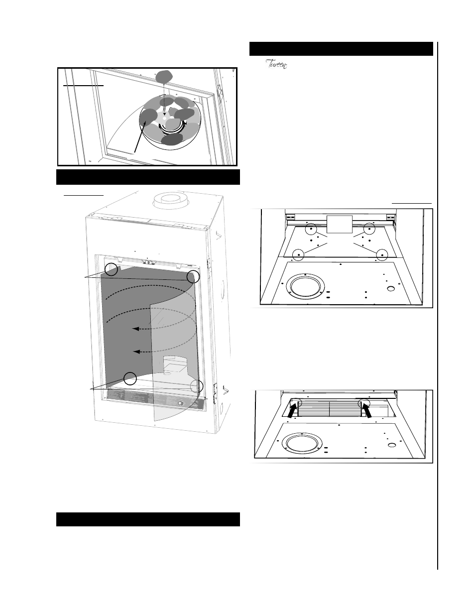
BLOWER REPLACEMENT
BLOWER
MOUNTING
PLATE
REMOVE 4 SCREWS
REMOVE 2 SCREWS
FIGURE 42