Napoleon Fireplaces DIRECT VENT MILLIVOLT SYSTEM BGD42N User Manual
Page 20
20
W415-0533 / E / 02.09.06
3. Tear the glowing embers into pieces and place along
the front row of ports covering all of the burner area in front of
the small logs (#2 & #3). Care should be taken to shred the
embers into thin, small irregular pieces as only the exposed
edges of the fibre hairs will glow. The ember material will
only glow when exposed to direct flame; however, care should
be taken to not block the burner ports. Blocked burner ports
can cause an incorrect flame pattern, carbon deposits and
delayed ignition. PHAZER
TM
logs glow when exposed to
direct flame.
4. Cradle the notch on the bottom of the left crossover log
(#4) around the left side of the grate and the top into the
pocket provided on the back log. Place the end of the center
log (#5) against the grate, as shown, with the other end of
the log resting in the pocket of the left crossover log.
5. Place the bottom of the right crossover log (#6) against
the right side of the grate. Place the top into the pocket
provided on the center log (#5).
PHAZER
TM
logs and glowing embers, exclusive to Napo-
leon Fireplaces, provide a unique and realistic glowing ef-
fect that is different in every installation. Take the time to
carefully position the glowing embers for a maximum glow-
ing effect. Log colours
may vary. During the initial use of the
fireplace, the colours will become more uniform as colour
pigments burn in during the heat activated curing process.
1. Place the cutout in the bottom of log #1 behind the pilot
assembly. Rest the log against the back wall of the firebox.
2. Move the two small logs (#2 & #3) into position, lining
up the studs located on the burner with the holes on the
bottom of the logs.
GLOWING EMBERS
LOG PLACEMENT
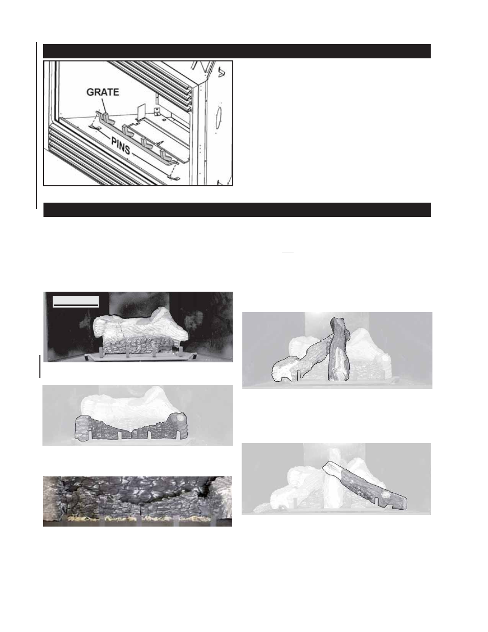
GRATE INSTALLATION
The grate for this fireplace has been removed for shipping
purposes.
The grate must be installed before the logs are installed.
Remove the packaging from the grate and install onto the
two pins as illustrated.
#2
#3
#4
#5
#6
#1
FIGURES 40a-d