Figure 1. scc-rly01 circuit diagram, Figure 2. high-voltage backshell, Specifications – National Instruments Relay Module SCC-RLY01 User Manual
Page 4: Electrical
SCC-RLY01 Relay Module User Guide
4
ni.com
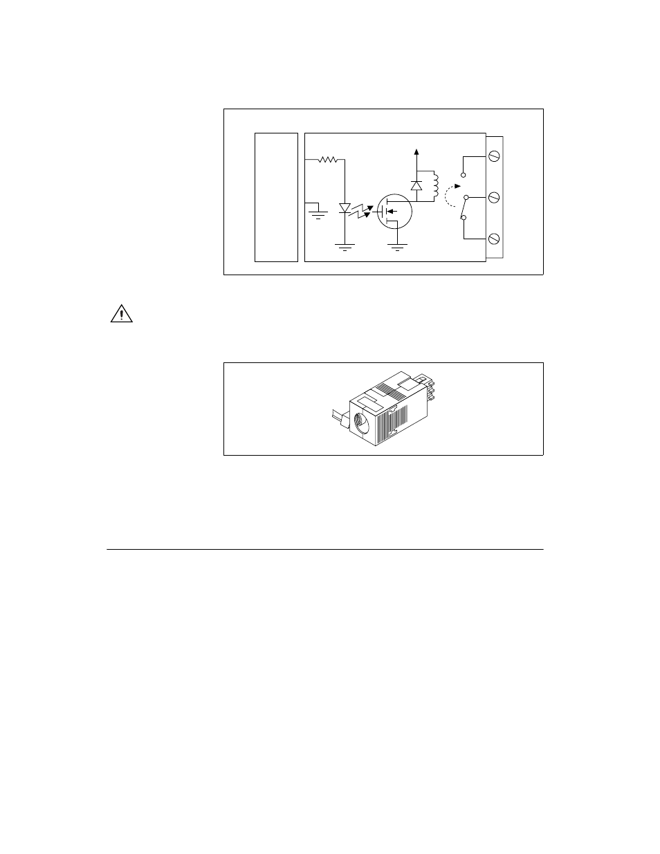
Figure 1. SCC-RLY01 Circuit Diagram
Caution
When connecting signals >60 VDC to the SCC-RLY01 module in the SCC-68,
you must use the high-voltage backshell. Figure 2 shows the high-voltage backshell.
Figure 2. High-Voltage Backshell
For information about how to configure the SCC-RLY01 module with
NI-DAQmx, refer to the SCC Quick Start Guide.
Specifications
These ratings are typical at 25 °C unless otherwise stated.
Electrical
Contact type ............................................SPDT (Form C), nonlatching
Nominal switching capacity
SCC-68 ............................................5 A at 250 VAC
5 A at 30 VDC
SC-2345...........................................5 A at 30 VAC
5 A at 30 VDC
SCC-RLY01
E/M Series
NO
NC
COM
+5 V
P0.(X )
D GND
1
2
3
390
Ω, 1/4 W