Figure 4-17. startscan output signal timing, Convert* signal -23, Figure 4-17. startscan output signal timing -23 – National Instruments PCI-6110E/6111E User Manual
Page 56: Convert* signal
Chapter 4
Signal Connections
© National Instruments Corporation
4-23
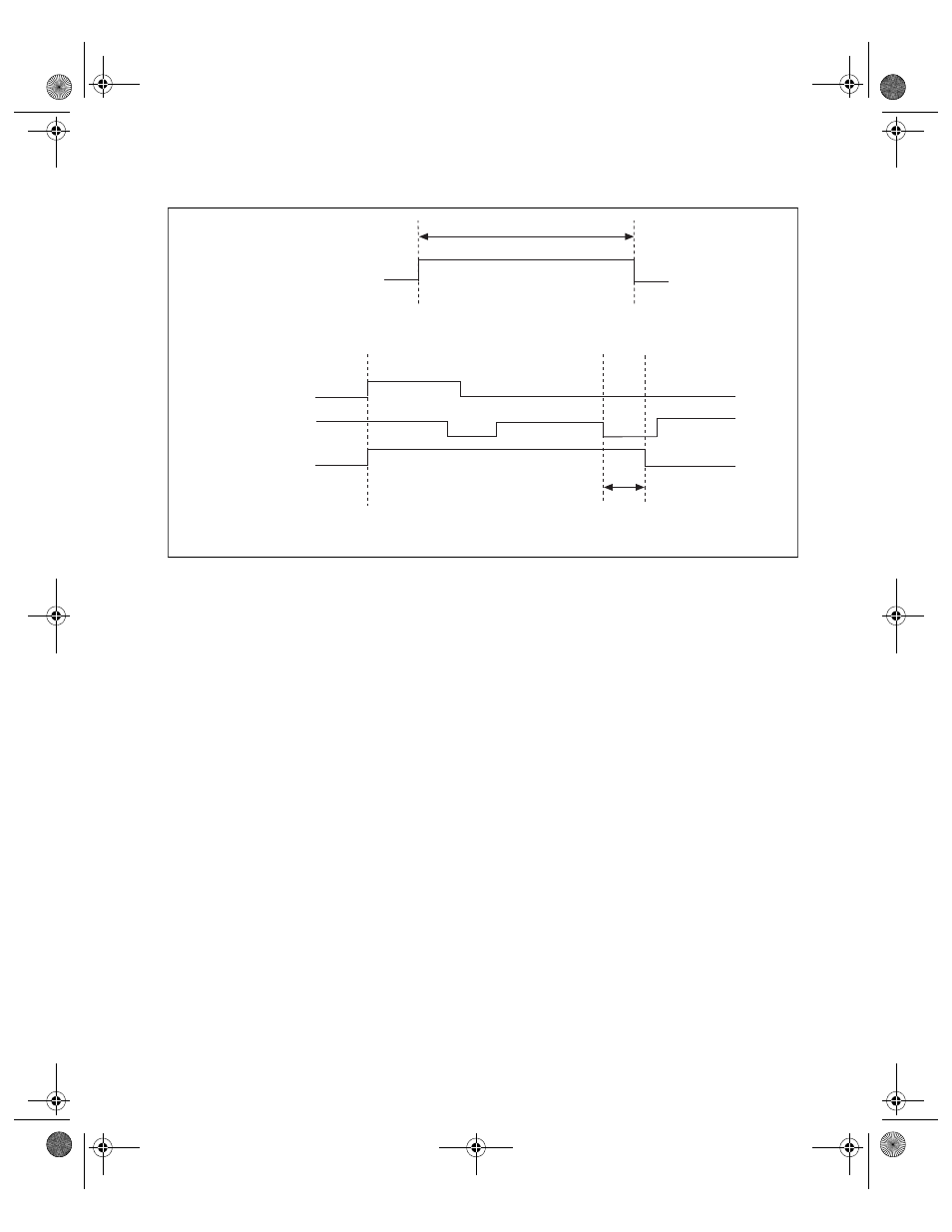
Figure 4-17. STARTSCAN Output Signal Timing
The CONVERT* pulses are masked off until the board generates the
STARTSCAN signal. If you are using internally generated conversions,
the first CONVERT* appears when the onboard sample interval counter
reaches zero. If you select an external CONVERT*, the first external
pulse after STARTSCAN generates a conversion. The STARTSCAN
pulses should be separated by at least one scan period.
A counter on the 611X E board internally generates the STARTSCAN
signal unless you select some external source. This counter is started by
the TRIG1 signal and is stopped either by software or by the sample
counter.
Scans generated by either an internal or external STARTSCAN signal
are inhibited unless they occur within a DAQ sequence. Scans occurring
within a DAQ sequence may be gated by either the hardware (AIGATE)
signal or software command register gate.
CONVERT* Signal
Any PFI pin can externally input the CONVERT* signal, which is
available as an output on the PFI2/CONVERT* pin.
a. Start of Scan
b. Scan in Progress, Two Conversions per Scan
toff
t
off
= 10 ns minimum
Start Pulse
CONVERT*
STARTSCAN
STARTSCAN
t
w
t
w
= 25-50 ns
PCI_E.book Page 23 Thursday, June 25, 1998 12:55 PM