Fireplace insert installation – Napoleon Fireplaces EPA 1900 User Manual
Page 7
7
W415-0282 / 09.05.01
OUTSIDE AIR
Connection from the stove's air intake to the outside is
mandatory in mobile homes only, either through a hole
in the wall to line up with the knockout in the pedestal
back, or through a hole in the floor to line up with the
hole in the pedestal base. Use a fresh air kit. Secure
the 4 inch diameter aluminum liner by flaring the end
once it is inserted through the 4-1/2 inch diameter hole
in either the back or base of the pedestal. If the air in-
take is through the floor, the hole in the pedestal back
must be covered with sheet metal to avoid cold air spill-
age into the room. A cover plate is available from your
Wolf Steel Ltd. dealer. Avoid cutting away floor joists,
wall studs, electrical wires or plumbing. Seal around
the outside pipe with insulation to prevent drafts.
If room air starvation occurs because the fresh air
intake is blocked with ice, leaves, etc., or because
the stove door was left open, or due to a strong
exhaust fan operating etc., dangerous fumes and
smoke from the operating stove could be drawn
into the room.
FIREPLACE INSERT
INSTALLATION
Your EPI 1101 and 1401 insert firebox is the exact
duplication of the clean-burning technology found in all
Napoleon EPA certified freestanding stoves and in par-
ticular that of the EPA 1100 and 1400. External modifi-
cations have been made to allow its installation as a
"functional fireplace insert" with a heat circulating blower
system and a means of enclosing the solid fuel burning
fireplace cavity for greater heating efficiency.
Your EPI 1401 fireplace insert may be installed only into a
solid fuel burning fireplace that is at least 14 inches deep
26 inches wide and 22 inches high with an approved lined
chimney at least 15 feet high (4.6m). The EPI 1101 insert
must be installed into a masonry fireplace at least 16 1/2
to 21 inches deep, 28 1/2 inches wide and 21 1/2 inches
high with an approved lined chimney at least 15 feet high
(4.6m). This minimum recess can only be achieved if the
opening height is sufficient enough to allow the connector
to fit under the noncombustible facing. The fireplace and
chimney must be constructed in accordance with all na-
tional and local building code standards.
HINT FOR INSTALLING PORCELAIN
ENAMEL INSERTS:
Ensure the base of the porcelain side pan-
els are protected from rubbing against the
hearth when sliding your insert into the
masonry fireplace.
PRIOR TO INSTALLATION
Clean all ashes out of the inside of the fireplace. Make
sure that the chimney and fireplace are free of cracks,
loose mortar, creosote deposits, blockage or other signs
of deterioration. If necessary, have any repair work done
by a qualified professional before installing the insert.
Do NOT remove bricks or mortar from the masonry
fireplace. In case of an outside air inlet or ash dump, fill
with fiberglass insulation. Adhere to minimum clear-
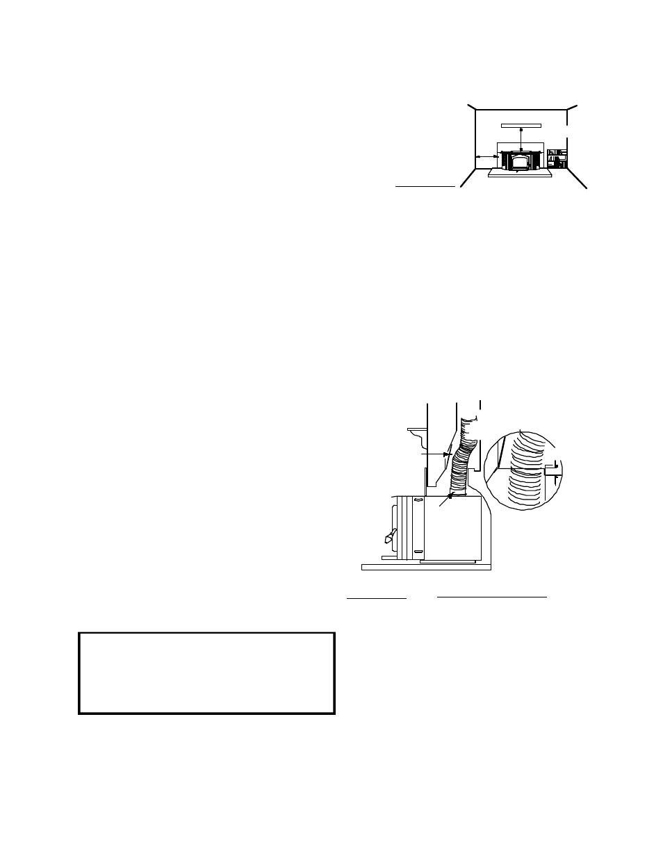
ances as shown in FIGURE 10.
Do NOT place any com-
bustible materials (furni-
ture, firewood, etc.)
within 48 inches in front
or 36 inches at the side
of the insert.
Combustible material must not protrude more that
1" to the side of the insert or between the mantle
and the top of the insert.
INSTALLATION INTO A MASONRY
FIREPLACE
1. Remove the fireplace damper or fasten it perma-
nently open.
2. Measure the throat of the fireplace and mark this
shape on a piece of 24 gauge sheet metal (flue cover);
cut a six-inch (150mm) hole to lie directly below the
fireplace flue opening. Allow two inches of material for
a flange on all sides and cut to these measurements.
Bend down the flanges. If you have never done this
before, it might be a good idea to make a cardboard
pattern and test it first. Fasten this flue cover in posi-
tion as high as possible with two masonry screws per
side through the flanges into the fireplace. FIGURE 11.
In Canada: Install a listed 6 inch diameter flexible
stainless steel liner from the top of the chimney to the
insert flue collar. Attach a stainless steel liner connec-
tor or elbow to the liner and insert onto the flue collar.
Fasten with three screws. Secure the top of the liner to
the chimney cap using a liner support and chimney
flashing. Cap the top of the chimney liner assembly
using an approved rain cap.
In the United States: While it is not required, it is
recommended that a chimney liner be installed that is
continuous from the insert to the top of the chimney,
particularly when the insert is installed in a basement.
For this type of connection, use the "In Canada" instal-
lation instructions above.
FIGURE 10
FIGURE 11
MODEL 1401 Illustrated