Identification of controls, Rear panel – NAD C715 User Manual
Page 9
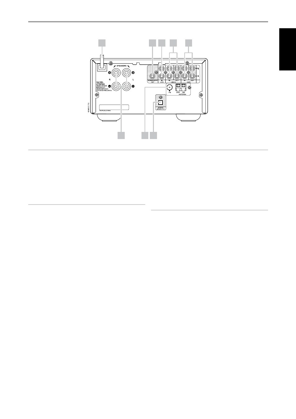
1 SPEAKERS: Connect the left and right terminals to the corresponding
loudspeakers. Make sure that the “+” (red) terminal and “-” (black)
terminal are connected to the corresponding “+” and “-” terminals of the
loudspeaker. Use extra care to ensure that no stray wires or strands cross
between posts or terminals at either end.
NOTES
• Use stranded wire of at least 16-gauge (AWG); specialized speaker cable
may be valuable (consult your NAD audio specialist). Connections to the
C 715 can be made with banana-type plugs, or using bare wire, or pins,
by loosening the terminal’s plastic nut, making a clean, neat connection,
and re-tightening carefully. To minimize the danger of short-circuits,
ensure that only 1/2-inch of exposed wire or pin is employed in
connecting.
• This unit is designed to produce optimum sound quality when
connected to speakers with impedances within the receiver’s operating
range. Please check that speakers are rated to be 6 ohms minimum per
speaker.
2 FM, AM ANTENNA INPUT: Connect the supplied lead-type FM
antenna to the FM antenna input. Extend the lead. Experiment freely
with your antenna placement and orientation until you get the clearest
sound and lowest background noise. Fix the antenna in the desired
position by using thumb tacks, push pins or any suitable means.
The AM loop antenna supplied with the C 715 (or a suitable
replacement) is required for AM reception. open the clip terminal
lever; insert the wire making sure to match the color-coded (white
and black) ends of the wire to that of the terminal and close the
lever ensuring that the lever locks the wire in place. Testing different
positions for the antenna may improve reception; vertical orientation
will usually produce the best results. Antenna proximity to large metal
objects (appliances, radiators) may impair reception, as will attempts to
lengthen the wire to the loop.
3 OPTICAL DIGITAL OUT: Connect the oPTICAl DIGITAl oUT port to
the corresponding S/PDIF digital input of a compatible device such as
CD recorders, receivers, computer soundcard or other digital processors.
4 TAPE IN/OUT: Connections for analog recording and playback to an
audio tape recorder of any type. Using twin RCA-to-RCA leads, connect
the left and right “Audio output” of the tape machine to the C 715’s
TAPE IN sockets for playback and tape monitoring. Connect the left and
right “Audio Input” of the tape machine to C 715’s TAPE oUT sockets for
recording.
NOTE
There will be no output at TAPE OUT when TAPE is selected. Likewise,
there will be no output at VIDEO OUT when VCR is the active source
input. This prevents feedback through the recording component thereby
preventing possible damage to your speakers.
5 VCR IN/OUT: VCR may be used with recording components such
as a cassette deck. Connect analog stereo audio from such source
components into the C715’s VCR IN. Connect the C 715’s VCR oUT to
the source components’ record-input. Note that VCR may freely be used
for play-only components, in which case the oUT jacks would remain
unconnected.
6 AUX IN: Input for additional line level input such as another CD player.
Use a twin RCA-to-RCA lead to connect the auxiliary unit’s left and right
“Audio output” to this input.
7 SUBWOOFER OUT: Connect this output to a powered (“active”)
subwoofer (or to a power amplifier channel driving a passive system).
8 AC LINE CORD: Plug the AC power cord into a live AC wall socket.
Make sure all connections have been made before connecting to mains.
IDENTIFICATION OF CONTROLS
REAR PANEL
ATTENTION!
Please make sure that the C 715 is powered off or unplugged before making any connections. It is also advisable to power down or unplug all associated
components while making or breaking any signal or AC power connections.
8
7
6
5
4
1
3
2
9
EN
G
LI
SH
FR
ANÇ
AIS
ESP
AÑOL
IT
ALIANO
DEUT
SCH
NEDERL
ANDS
SVENSK
A
РУ
ССКИЙ