Part names and functions, Rear view front view 3, 11 terminal board 4 – NEC XV29 Plus User Manual
Page 7
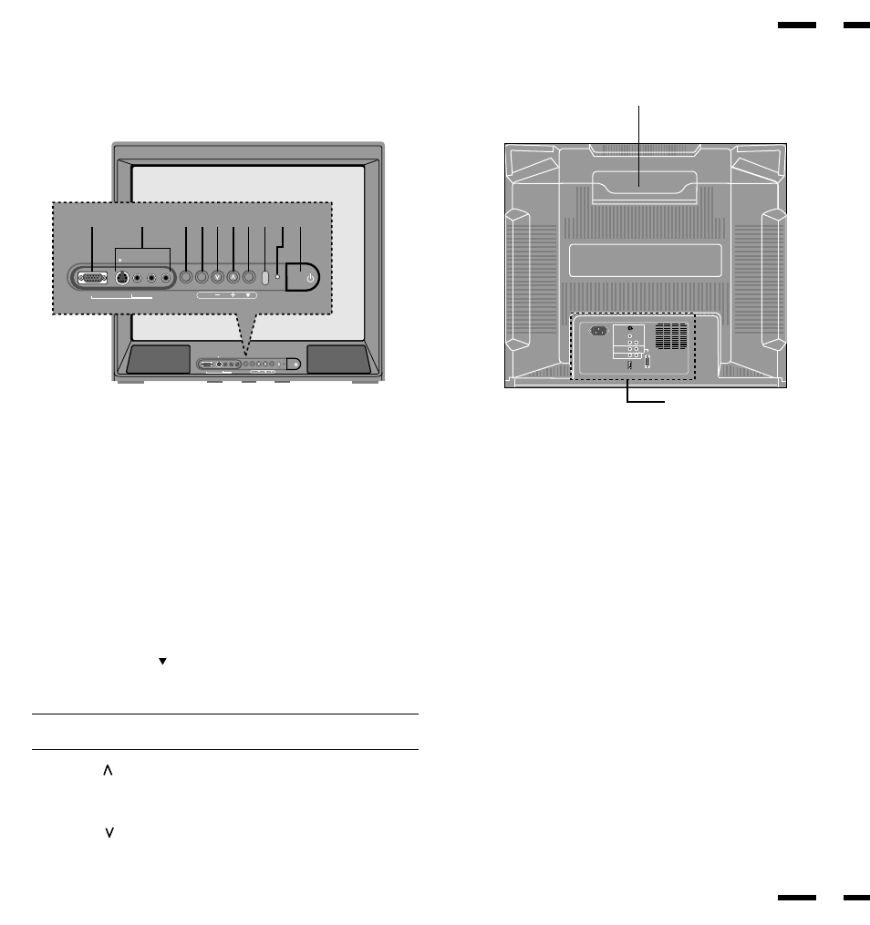
Rear View
Front View
3
Part Names and Functions
1 POWER
Press to turn the main power on and off when the AC power is supplied.
2 POWER/STANDBY
When this indicator is green, the monitor is on; when the indicator is amber,
it is in standing by.
3 Remote Sensor Window
Receives infrared signal from the handheld remote control.
4 SOURCE SELECT ( )
Press to select VIDEO 1, VIDEO 2, RGB 1 or RGB 2 video source. When
you are in the OSM mode, this button works as the down button.
NOTE: S-VIDEO IN terminals will take preference over VIDEO IN terminals
when the video source is connected to each terminal and VIDEO 1 or 2 selected.
5 VOLUME ( / +)
Used to increase the volume. When you are in the OSM mode, this button
works as the plus button.
6 VOLUME ( / –)
Used to decrease the volume. When you are in the OSM mode, this button
works as the minus button.
7 EXIT
Press to exit the OSM mode. The OSM screen disappears.
8 PROCEED
Press to access OSM. The OSM screen is displayed.
9 VIDEO 2
VIDEO 2 IN (RCA type) ........ Connect a VCR or laser disk player here to
display the video.
S-VIDEO 2 IN ........................ Here is where you connect S-Video input
from an external source like a VCR.
AUDIO R IN .......................... This is your right channel audio input for
stereo sound coming from video 2 or RGB 2
input, or audio system.
AUDIO L IN (MONO) ........... This is your left channel audio input for
stereo sound coming from video 2 or RGB 2
input, or audio system. It also serves as the
mono audio input.
10 RGB 2 Input(D-Sub mini 15 pin)
Connect your PC or other RGB equipment such as IBM or compatible
computers.
11 Remote Control Holder
Place remote control unit here when not in use.
POWER
POWER
/STANDBY
SOURCE SELECT
VOLUME
RGB2
VIDEO2
S
L (MONO) R
AUDIO
PROCEED
EXIT
POWER
POWER
/STANDBY
SOURCE SELECT
VOLUME
RGB2
VIDEO2
S
L (MONO) R
AUDIO
PROCEED
EXIT
1
2
3
4
5
6
7
8
9
10
ON
1
2
3
4
56
AC-IN
VIDEO1
DIP SW
RGB 1
AUDIO1
IN
R
R
R
L
L
L
RGB
AUDIO IN
MONITOR
OUT
(MONO)
(MONO)
11
Terminal Board
4