Gas furnace components – Nordyne iSEER FG7T User Manual
Page 2
2
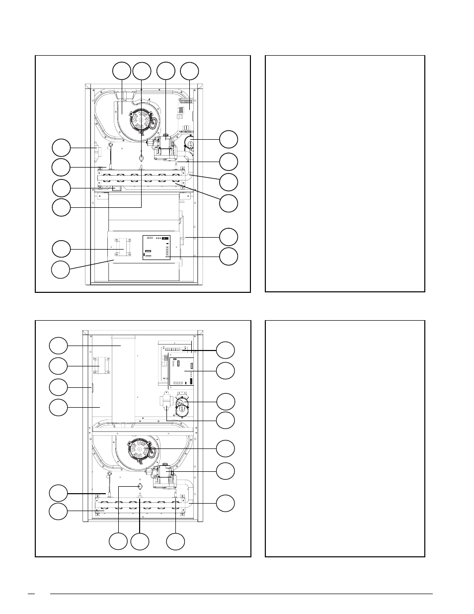
Downflow Gas Furnace
GAS FURNACE COMPONENTS
Upflow/Horizontal Gas Furnace
12
34
56
78
9
6
8
3
15
1
10
16
11
4
5
7
12
13
2
14
1
2
3
4
5
6
7
8
15
16
7
6
8
9
3
11
4
2
13
12
14
10
5
1
1. Blower Assembly
2. Blower Door Switch
3. Burner Assembly
4. Combustion Tube
5. Flame Roll-Out Switch
6. Flame Sensor
7. Furnace Control Board
8. Gas Manifold
9. Gas Valve
10. Igniter
11. Inducer Assembly
12. Main Air Limit Switch
13. Motor Choke (3/4 and 1HP only)
14. Motor Control Board
15. Pressure Switch(s)
16. Transformer
1. Blower Assembly
2. Blower Door Switch
3. Burner Assembly
4. Flame Roll-Out Switch
5. Flame Sensor
6. Furnace Control Board
7. Gas Manifold
8. Gas Valve
9. Igniter
10. Inducer Assembly
11. Main Air Limit Switch
12. Motor Choke (3/4 and 1HP only)
13. Motor Control Board
14. Motor Control Box
15. Pressure Switch(s)
16. Transformer