Bgd36cfg light switch / wiring diagram – Napoleon Fireplaces BGD36CFPTR User Manual
Page 36
36
W415-0661 / C / 02.20.08
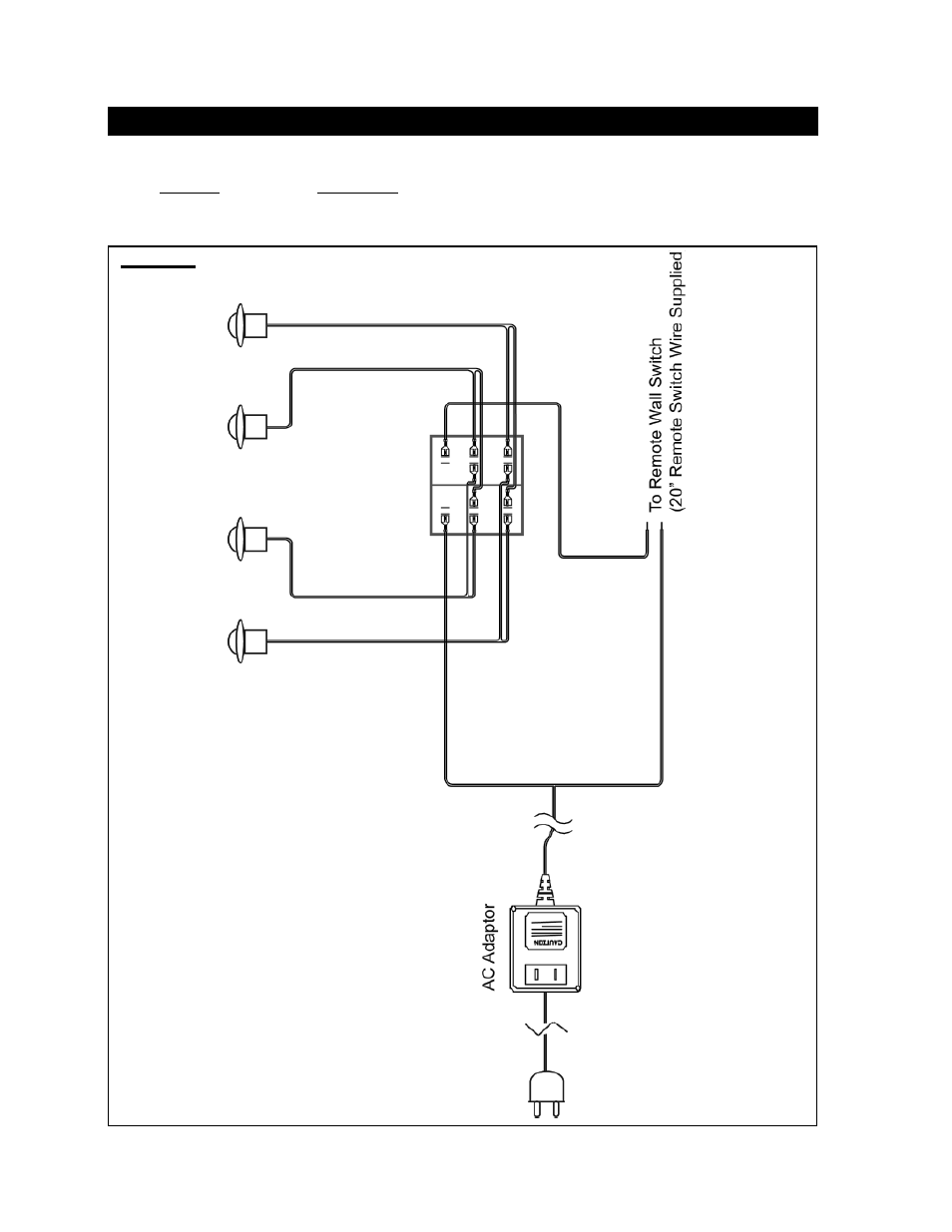
BGD36CFG LIGHT SWITCH / WIRING DIAGRAM
FIGURE 126
A wall switch must be installed in a convenient location for the light
operation.
The recommended maximum lead length depends on wire size:
WIRE SIZE
MAX. LENGTH
14 gauge
100 feet
16 gauge
60 feet
18 gauge
40 feet
A 20’ length of millivolt wire is connected to the gas valve for the
light wall switch. However if a greater length is required route 2-
strand (solid core) wire through the electrical hole located at the
bottom left side of the unit.
This manual is related to the following products: