Bgd36cfg burner switch / wiring diagram – Napoleon Fireplaces BGD36CFPTR User Manual
Page 35
35
W415-0661 / C / 02.20.08
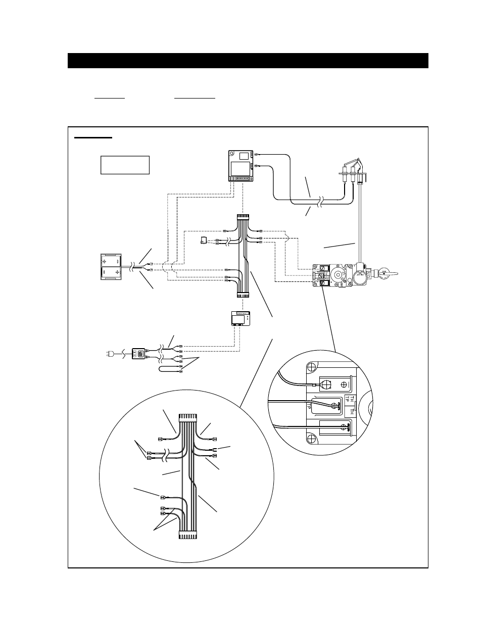
BGD36CFG BURNER SWITCH / WIRING DIAGRAM
A wall switch must be installed in a convenient location for the burn-
er operation.
The recommended maximum lead length depends on wire size:
WIRE SIZE
MAX. LENGTH
14 gauge
100 feet
16 gauge
60 feet
18 gauge
40 feet
A 20’ length of millivolt wire is connected to the gas valve for the
burner wall switch. However if a greater length is required route
2-strand (solid core) wire through the electrical hole located at the
bottom left side of the unit.
FIGURE 125
B
ATTERY
H
OLDER
G
AS
V
ALVE
P
ILOT
A
SSEMBLY
I
GNITION
M
ODULE
P
ILOT
G
AS
L
INE
Orange
(I)
[through
independent
conduit]
Yellow
(S)
[through
Gas line
conduit]
AC A
DAPTOR
B
ATTERY
R
ELAY
Red (3 Volt)
Red
Black
W
IRE
H
ARNESS
N
OTE
: W
IRE TAGS
ARE BRACKETED
Brown
(SWI)
Black
(-)
Red
(+)
Green x2
(TH)
Orange x2
(THTP)
Black
Yellow
Blue
Black
(TP)
M
ODULE
P
LUG
R
ELAY
P
LUG
Black
Green
Orange
B
LACK
(12 Volt)
T
O
L
IGHT
&
L
IGHT
TM
S
WITCH
(20’ R
EMOTE
S
WITCH
W
IRE
S
UPPLIED
)
M
AIN
B
URNER
S
WITCH
(20’ R
EMOTE
S
WITCH
W
IRE
S
UPPLIED
)
*
Main Burner Switch