Markers, Table 8 – National Instruments NI 5412 User Manual
Page 15
© National Instruments Corporation
15
NI 5412 Specifications
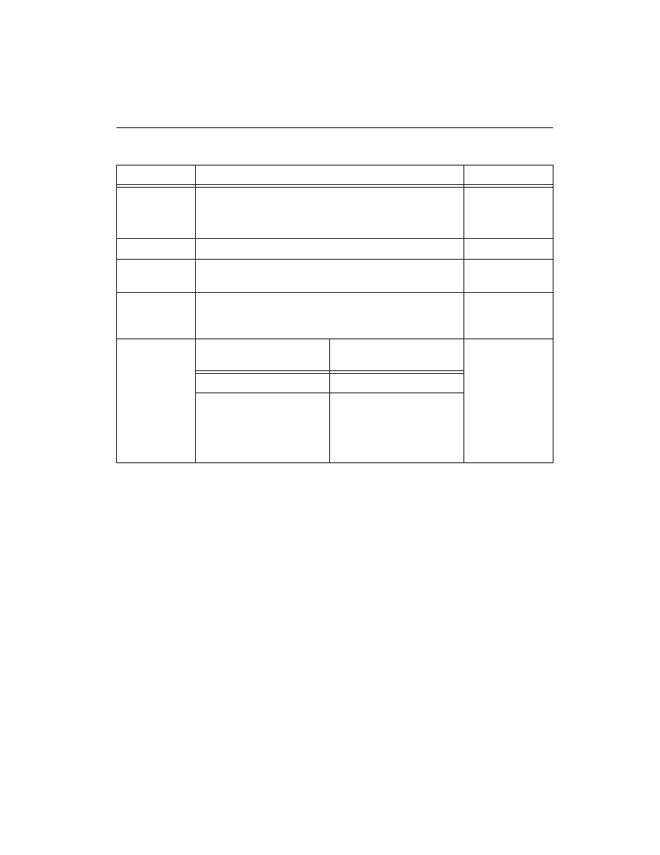
Markers
Table 8.
Specification
Value
Comments
Destinations
1. PFI<0..1> (SMB front panel connectors)
2. NI PXI-5412—PXI_Trig<0..6> (backplane connector)
NI PCI-5412—RTSI<0..6>
—
Quantity
One Marker per Segment.
—
Quantum
Marker position must be placed at an integer multiple of
four samples.
—
Width
>150 ns. Refer to t
m2
at NI Signal Generators Help»
Devices»NI 5412»NI
Generation»Marker Events
—
Skew
Destination
With Respect to Analog
Output
Refer to t
m1
at
NI Signal
Generators
Help»Devices»
NI 5412»
NI
Waveform
Generation»
Marker Events
PFI<0..1>
±2 Sample Clock Periods
NI PXI-5412
PXI_Trig<0..6>
NI PCI-5412 RTSI<0..6>
±2 Sample Clock Periods