Digital ds3/e3 tap quick installation diagram – Network Instruments WAN Probe Kit User Manual
Page 11
Getting Started
5
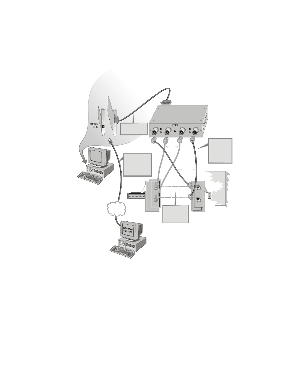
Digital DS3/E3 TAP Quick Installation Diagram
Frame
Relay
Card
A
Probe
Service
Running
TCP/IP
LAN
T X
R X
T X
R X
DS3 Line
(DCE)
IN
OUT
DS3
TAP
B
A
DTE
DCE
LOS
LOF
LOS
LOF
POWER
LOS
LOF
LOS
LOF
IN
OUT
IN
OUT
CSU/DSU
(DTE)
Move the DCE
connectors from
the DS3 line to
the &
ports on the TAP.
IN OUT
Use the
supplied DS3
cable to
complete the
passthrough
Link back to the
DS3 Line.
Use the supplied
10/100 cable to
connect the Probe
to a TCP/IP LAN
with an Observer
system attached.
Connect Interface
card to TAP with
Interface cable.
2
Install the
Network
Instruments
Probe
software.
3
From the Observer
Console, the newly-
configured Probe will
now be available on
Observer’s Probe List.
1
Install the interface cards,
drivers, and cabling.
OUT (TX)
IN (RX)
OUT (TX)
IN (RX)
Original DS3 link
connection
Move
DS3
link
cables to
TAP
Supplied
cables
completing
passthru
(TX)
(RX)
(TX)
(RX)