Setup block diagram, Shotbox a, Shotbox b – Pinnacle Speakers Lightning 1000 User Manual
Page 29: Lightning chassis, Lightning 1000 installation guide
23
Lightning 1000 Installation Guide
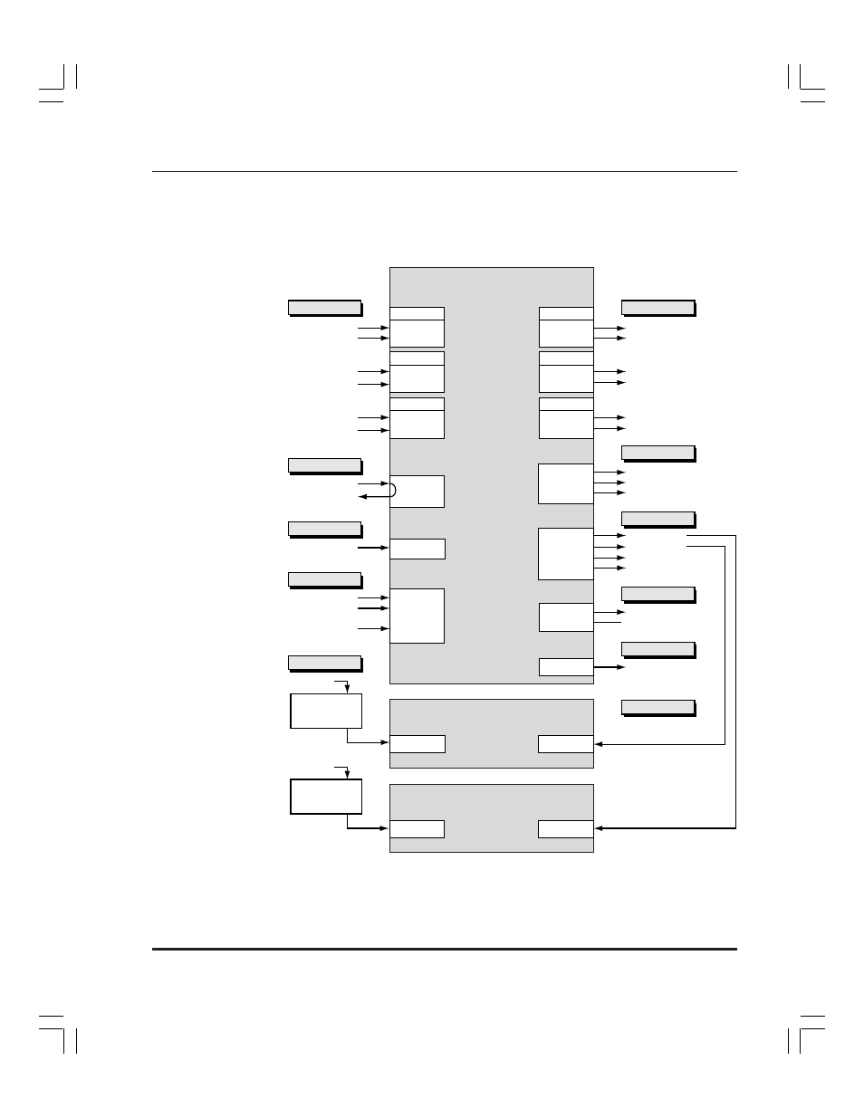
Setup Block Diagram
For reference in the following procedures, a simplified system block
diagram of a Digital system is provided below. Lightning chassis connector
names are listed inside the Lightning chassis block.
Video Inputs
Digital
Input Sources
Digital
Input Sources
Video Outputs
To Monitor, Routing Switcher
To Routing Switcher
To Monitor, Routing Switcher
To Routing Switcher
Display
To SVGA Monitor
To Y/C Video Monitor
To Composite Video Monitor
Reference
House Reference
(75 ohm Terminator
or Loop)
Power
Power
AC Power
AC Power
Control
Mouse
Keyboard
PC Network
(10-baseT or 100-baseT)
Universal
Power Supply
DC Power
(optional)
ShotBox A
Power
AC Power
Universal
Power Supply
DC Power
(optional)
ShotBox B
Power
Control
Control
To ShotBox A
To ShotBox B
To Automation system
To Automation system
Digital
Digital
Video
Key
Video
Key
Digital
Digital
Video
Key
Video
Key
Channel 1
(standard)
Channel 2
(optional)
Digital
Input Sources
To Monitor, Routing Switcher
To Routing Switcher
Digital
Video
Key
Digital
Video
Key
Channel 3
(optional)
Lightning
Chassis
SVGA
Y/C
Comp
In
Out
AC In
Mouse
Keyboard
Network
RS422-A
RS422-B
RS422-C
RS422-D
GPI-A
GPI-B
To Automation system
(Not Implemented)
GPI
SCSI
SCSI
RS422
RS422
To SCSI Devices