Installation/ еумъ‡к, Cq-c7405w, Model – Panasonic CQ-C7405W User Manual
Page 41: How to install the unit/ д‡н тпумълу‚‡ъ¸ фл·у, How to remove the unit/ д‡н òìflú¸ фл·у, English кыттнли
CQ-C7405W Installation Instructions YFM294C092CA
(1)
OPEN
DISP
BAND
CQ-C7405W
TILT
/SET/APM
SQ
MENU
TUNE
TRACK
MUTE
SBC-SW
FOLDER /P-SET/DISC
LIST
SOURCE
PWR
/
VO
L
PUS
H SEL / S
RSW
OW
D
・
M
4
e
w
TEXT
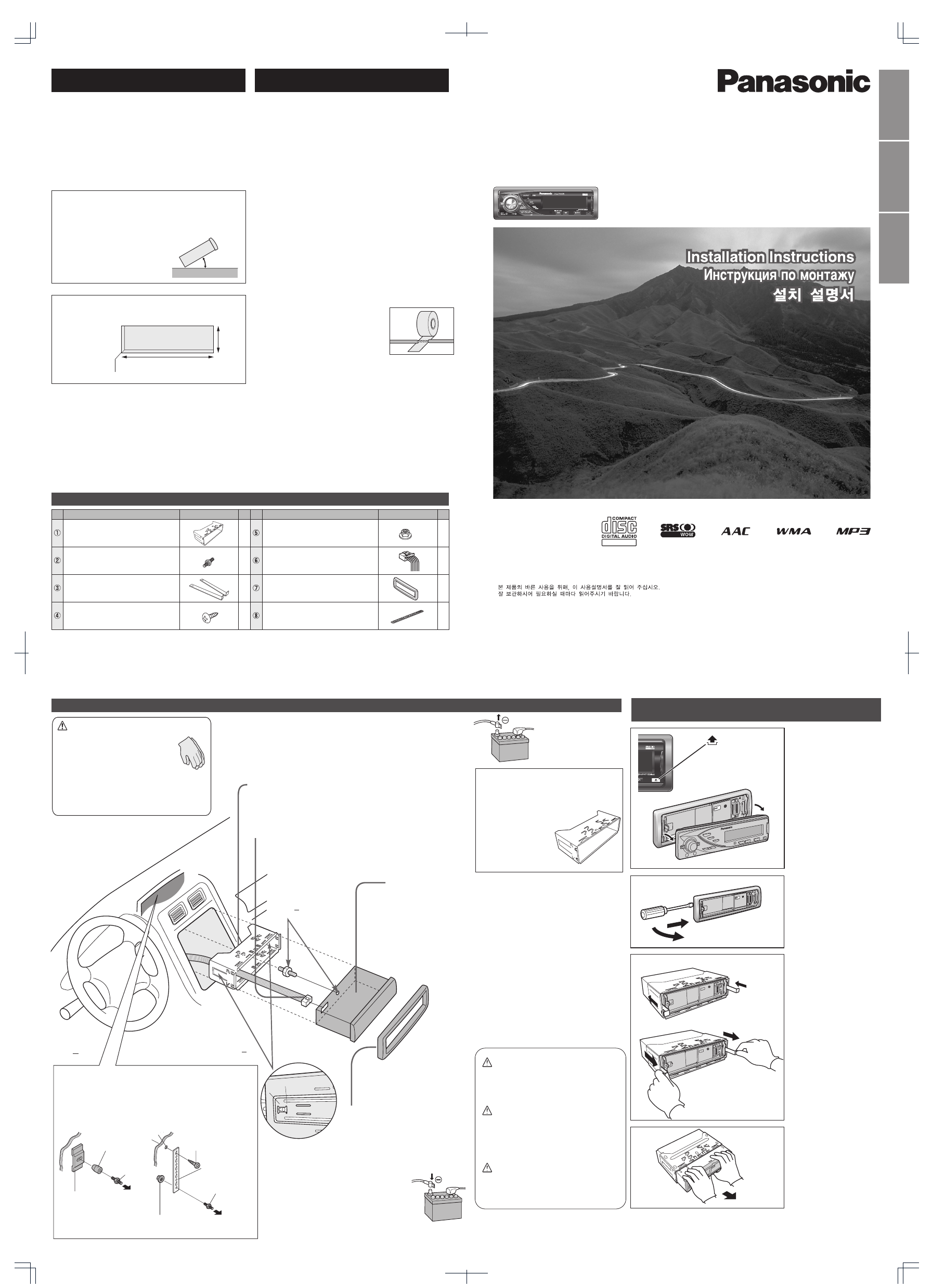
How to install the unit/
д‡Н ТПУМЪЛУ‚‡Ъ¸ ФЛ·У/
Installation/
еУМЪ‡К/
Mounting collar q insertion. Bend mounting tabs.
ЗТЪ‡‚ОВМЛВ ПУМЪ‡КМУИ ‡П˚ q. ᇄ˷‡˛Ъ ПУМЪ‡КМ˚В О‡ФНЛ.
q
Connection of power connector y
иУ‰ТУВ‰ЛМВМЛВ ТЛОУ‚У„У ‡Б˙ВП‡ y
y
5
Trim plate u mounting
мТЪ‡МУ‚Н‡ У·‡ÏÎÂÌËfl u
u
6
Battery cable reconnection
иУ‚ЪУМУВ ФУ‰ТУВ‰ЛМВМЛВ Н‡·ВОfl Н ·‡Ъ‡ВВ
How to remove the unit/
д‡Н ÒÌflÚ¸ ФЛ·У/
Cautions
●
Wear gloves for safety.
●
Make sure that wiring is completed
before installation.
ЗМЛП‡МЛВ
●
лОВ‰ЫВЪ М‡‰ВЪ¸ ФВ˜‡ЪНЛ ‰Оfl
·ВБУФ‡ТМУТЪЛ.
●
лОВ‰ЫВЪ Ы·В‰ЛЪ¸Тfl, ˜ЪУ ПУМЪ‡К
˝ОВНЪУФУ‚У‰УН Б‡‚В¯ВМ ‰У
ПУМЪ‡К‡ ФЛ·У‡.
●
●
Remove the cable from the battery negative terminal.
йЪТУВ‰ЛМfl˛Ъ Н‡·ВО¸ УЪ УЪЛˆ‡ЪВО¸МУ„У ‚˚‚У‰‡ ·‡Ъ‡ВЛ.
Bend appropriate tabs to secure the unit
without backlash.
ᇄ˷‡МЛВП ТУУЪ‚ВЪТЪ‚Ы˛˘Лı О‡ФУН ЩЛНТЛЫ˛Ъ
ФЛ·У ·ВБ Б‡БУ.
q Screw the mounting bolt w into the main unit.
w Secure to the fire wall.
e Snap the right and left springs into each hole.
q ᇂВЪ˚‚‡˛Ъ mÓÌÚ‡КМ˚И ·УОЪ w ‚ „О‡‚М˚И ·ОУН.
w дВФОВМЛВ Н ÚÂÔÎÓËÁÓÎflˆËÓÌÌÓÈ Ф‡МВОЛ.
e З‚У‰flЪ Ф‡‚Ы˛ Л ОВ‚Ы˛ ФЫКЛМ˚ ‚ УЪ‚ВÒÚËfl ÔÓ‰ ÌËı.
q
w
w
e
Main unit securing
дВФОВМЛВ „О‡‚МУ„У
·ОУН‡
4
Securing to fire wall
дВФОВМЛВ Н ÚÂÔÎÓËÁÓÎflˆËÓÌÌÓÈ Ф‡МВОЛ
Using the rear support strap i
л ФУПУ˘¸˛ Б‡‰МВИ УФУМУИ ФО‡МНЛ i
i
Using the rubber bushing (Option)
л ФУПУ˘¸˛ ВБЛМУ‚УИ ‚ЪЫОНЛ (ФУ ÓÔˆËË)
3mm
Tapping screw r
л‡ПУМ‡ВБ‡˛˘ЛИ ‚ЛМЪ r
r
To the unit
д ФЛ·УЫ
To the unit
д ФЛ·УЫ
Rear support strap i
ᇉМflfl УФУМ‡fl ФО‡МН‡ i
i
Hexagonal nut t
тВТЪЛ„‡ММ‡fl „‡È͇ t
t
Rear support bracket
(supplied with car)
ᇉМЛИ УФУМ˚И НУМ¯ЪВИМ
(ФУТЪ‡‚ÎflÂÏ˚И Т ‡‚ЪУПУ·ЛОВП)
Rubber Bushing (Option)
кВБЛМУ‚‡fl ‚ЪЫОН‡ (ФУ ÓÔˆËË)
Mounting Bolt w
еУМЪ‡КМ˚И ·УОЪ w
w
Caution
When this unit is installed in dashboard,
ensure that there is sufficient air flow
around the unit to prevent damage from
overheating, do not block any ventilation
holes on the unit.
ЗМЛП‡МЛВ
иЛ ПУМЪ‡КВ М‡ÒÚÓfl˘В„У ЫТЪУИТЪ‚‡ М‡ Ф‡МВО¸
ФЛ·УУ‚ ТОВ‰ЫВЪ У·ВТФВ˜ЛЪ¸ ‰УТЪ‡ЪУ˜М˚И ФУЪУН
‚УБ‰Ыı‡ ‚УНЫ„ МВ„У ‚У ЛБ·ВК‡МЛВ В„У
ФУ‚ВК‰ÂÌËfl ЛБ-Б‡ ФВ„‚‡, ФЛ˜ВП МВ
ТОВ‰ЫВЪ Б‡Н˚‚‡Ъ¸ ‚ÂÌÚËÎflˆËÓÌÌ˚В УЪ‚ВÒÚËfl
ЫТЪУИТЪ‚‡.
Mounting Bolt w
еУМЪ‡КМ˚И ·УОЪ w
w
Remove the face plate.
лМЛП‡˛Ъ ÎËˆÂ‚Ы˛ Ф‡МВО¸
ФЛ·У‡.
1
Remove the trim plate
u
.
лМЛП‡˛Ъ У·‡ПМВМЛВ
u
.
u
2
3
Pull out the unit with
both hands.
З˚Ъ‡ТНЛ‚‡˛Ъ У·ВЛПЛ
ЫН‡ПЛ ФЛ·У.
4
Clank!
1
2
3
4
4
4
5
6
q
4
Lock release
q Insert the lock cancel plate
e until you hear a click.
w Pull the main unit.
ëÌflÚË ТЪУФУÂÌËfl
q ÇÒÚ‡‚Оfl˛Ъ ФО‡ТЪЛМЫ ÒÌflÚËfl
ТЪУФУÂÌËfl e ‰У ˘ВО˜Н‡.
w TflÌËÚe „Оa‚МЫ˛ e‰ËÌˈÛ.
q
e
w
0 – 30
°
53 mm
182 mm
4.5 mm – 6.0 mm
AAC WMA MP3 CD Player/Receiver
AAC WMA MP3 CD-ФОВВ/ВТЛ‚В
Model:
CQ-C7405W
●Please read these instructions carefully before using this product and keep this manual for future reference.
●иВВ‰ М‡˜‡ОУП ˝НТФОЫ‡Ъ‡ˆЛЛ ФУТЛП ФУ˜ЛЪ‡Ъ¸ М‡ÒÚÓfl˘Ы˛ ЛМТЪÛÍˆË˛ ‚МЛП‡ЪВО¸МУ Л ı‡МЛЪ¸ ВВ М‡ ФУО¸БУ‚‡МЛВ М‡ ·Ы‰Ы˘ВВ.
●
YFM294C092CA NY1006-1116 Printed in China
Matsushita Electric Industrial Co., Ltd.
Web Site: http://panasonic.net
Consult a professional for installation.
●
Verify the radio using the antenna and speakers before installation.
иУ ‚УФУТЫ ПУМЪ‡К‡ ТОВ‰ЫВЪ У·‡˘‡Ъ¸Тfl Н ÒÔˆˇОЛТЪЫ.
●
иВВ‰ ПУМЪ‡КУП ФУ‚Вfl˛Ъ ‡‰ЛУФЛВПМЛН Т ФУПУ˘¸˛
‡МЪВММ˚ Л „УПНУ„У‚УЛЪВОВИ.
●
●
Mounting angle side to side : horizontal
front to rear : 0 – 30
°
●
м„УО ПУМЪ‡К‡ ‚ ФУФВВ˜МУИ ФОУТНУТЪЛ : ЙУЛБУМЪ‡О¸
‚ ФУ‰УО¸МУИ ФОУТНУТЪЛ : 0 – 30°
●
°
●
Mounting space
●
иОУ˘‡‰¸ ФУ‰ ПУМЪ‡К
●
Before Installation/
иВВ‰ ПУМЪ‡КУП/
Before Wiring/
иВВ‰ ПУМЪ‡КУП ˝ОВНЪУФУ‚У‰УН/
Supplied Hardware/
СВЪ‡ОЛ, ‚ıУ‰fl˘ЛВ ‚ НУПФОВНЪ‡ˆЛ˛ ФУТЪ‡‚НЛ/
Exclusively operated with 12 V battery with
negative (–) ground.
Connect the power lead (red) last.
Connect the battery lead (yellow) to the positive (+) terminal of
the battery or fuse block terminal (BAT).
Strip about 5 mm of the lead ends for connection.
Apply insulating tape to bare leads.
Secure loosened leads.
к‡·УЪ‡ВЪ ЪУО¸НУ Т ФЛЪ‡МЛВП УЪ 12 V {B} ·‡Ъ‡ВЛ
Т УЪЛˆ‡ЪВО¸МУИ (–) БВПОВИ.
иУ‰ТУВ‰ЛМfl˛Ъ ТЛОУ‚УИ ‚˚‚У‰МУИ ФУ‚У‰ (Н‡ТМ˚И) ФУТОВ‰МЛП.
иУ‰ТУВ‰ЛМfl˛Ъ ‚˚‚У‰МУИ ФУ‚У‰ (КВОЪ˚И) Н ФУОУКЛЪВО¸МУПЫ (+) ‚˚‚У‰Ы
·‡Ъ‡ВЛ ЛОЛ НОВППВ ·ОУН‡ ФО‡‚НЛı ФВ‰Уı‡МЛЪВОВИ (BAT).
ë ÍÓ̈ӂ ‚˚‚У‰М˚ı ФУ‚У‰У‚ ТМЛП‡˛Ъ ËÁÓÎflˆË˛ М‡ ‰ОЛМВ УНУОУ 5
mm {ÏÏ} ‰Оfl ТУВ‰ËÌÂÌËfl.
з‡ У·М‡КВММ˚В ‚˚‚У‰М˚В ФУ‚У‰‡
М‡НО‡‰˚‚‡˛Ъ ËÁÓÎflˆËÓÌÌÛ˛ ОВМЪЫ.
оЛНТЛЫ˛Ъ УТО‡·ОВММ˚В ‚˚‚У‰М˚В ФУ‚У‰‡.
–
English
кЫТТНЛИ
*
w, e, r and t consist of a set. (YEP0FZ5739)
*
w, e, r
Ë t ТУТЪ‡‚Оfl˛Ъ НУПФОВНЪ. (YEP0FZ5739)
*
w, e, r
t
(YEP0FZ5739)
Remove mounting collar q and trim plate u from the main
unit temporarily, which are already mounted at shipment.
ЗВПВММУ ТМЛП‡˛Ъ Т „О‡‚МУ„У ·ОУН‡ ФЛ·У‡ ПУМЪ‡КМЫ˛ ‡ПЫ q Л
У·‡ПОВМЛВ u, ТПУМЪЛУ‚‡ММ˚В ФЛ УЪ„ЫБНВ.
q
u
Snapping point
MoÏeÌÚaθМ˚И cÌËÏoÍ
ÔÛÌÍÚa
q
w
q
w
1
No.
Diagram
Q'ty
Item
No.
Diagram
Q'ty
Item
Mounting collar
еУМЪ‡КМ‡fl ‡Ï‡
Mounting bolt (5 mmш)
еУМЪ‡КМ˚И ·УОЪ (5 mm {ПП} ш)
ш
Power connector
лЛОУ‚УИ ‡Б˙ВП
Hex. Nut (5 mm ш)
тВТЪЛ„‡ММ‡fl „‡È͇ (5 mm {ПП} ш)
ш
Trim plate
й·‡ПОВМЛВ
Rear support strap
ᇉМflfl УФУМ‡fl ФО‡МН‡
Tapping Screw (5 mm ø x 16 mm)
л‡ПУМ‡ВБ‡˛˘ЛИ ‚ЛМЪ (5 mm {ПП} ш x 16 mm)
ø x 16mm
FX0214C384ZB
✽
✽
✽
✽
Lock cancel plate
иО‡ТЪЛМ‡ ÒÌflÚËfl ТЪУФУÂÌËfl
YFG044C002ZA
1
2
1
1
1
1
1
YEFC051013
YGAJ021011
e
w
q