Patton electronic MODEL 2707/I User Manual
Page 14
14
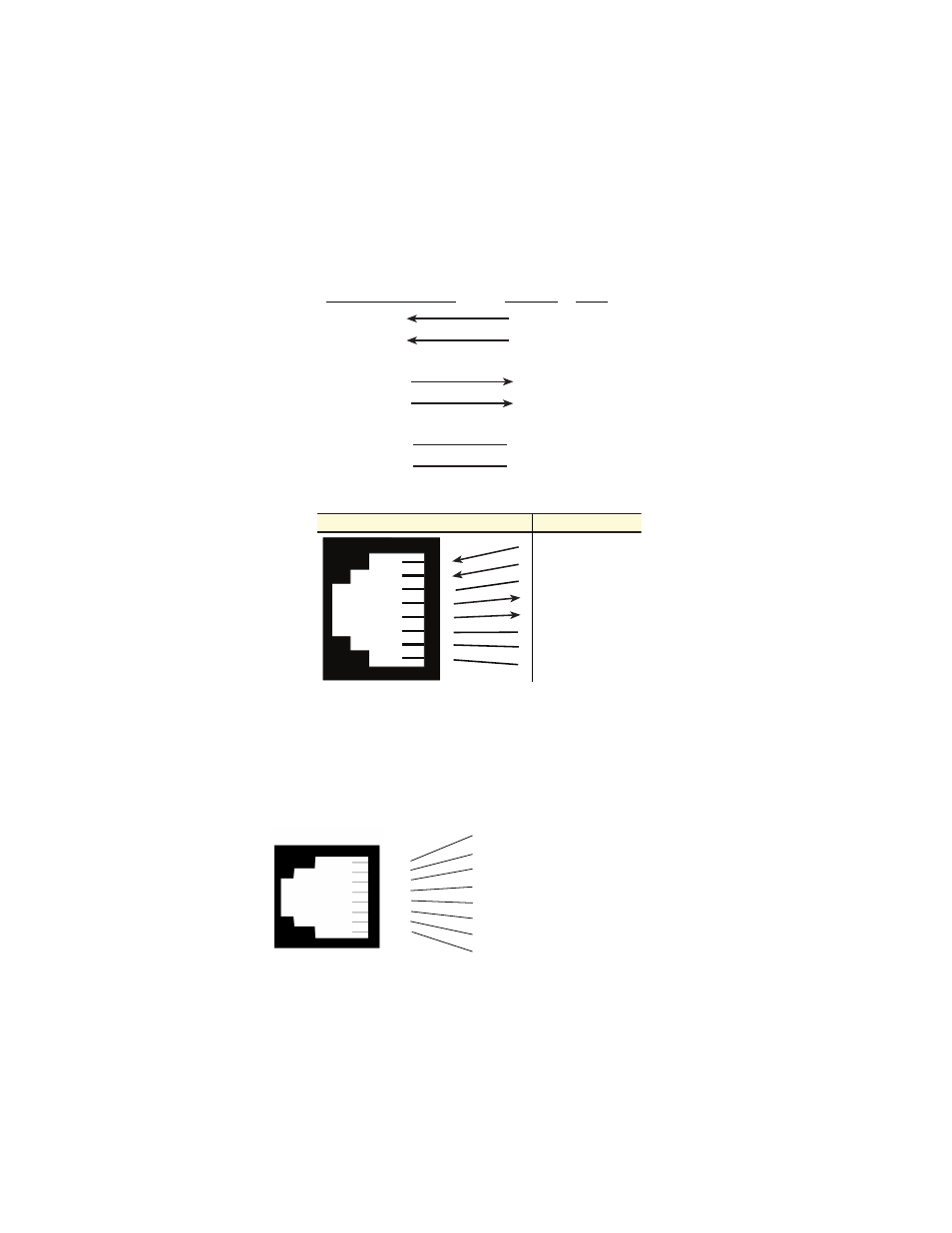
Connecting the Twisted Pair (120 ohm) to the G.703 Network
Refer to the pinout and signals chart in Figure 6 to connect the 120-ohm
G.703 network channel.
Figure 6.
G.703 120-ohm connection.
Connecting the 10Base-T Ethernet port to a PC (DTE)
To connect the Model 2707/I to another DTE device such as a 10Base-T
network interface card, construct a 10Base-T crossover cable and con-
nect the wires as shown in Figure 7 below and Figure 8 on page 15.
Figure 7.
Connecting the 10Base-T Ethernet Port to a PC
NETWORK SIGNAL
SIGNAL
PIN#
RX(R)
RX(T)
TX(R)
TX(T)
Shield
Shield
4
5
1
2
3
6
TX(R)
TX(T)
RX(R)
RX(T)
Shield
Shield
1
2
3
4
5
6
7
8
1
2
3
4
5
6
7
8
(RX) Receive (Ring)
(RX) Receive (Tip)
Shield
(TX) Transmit (Ring)
(TX) Transmit (Tip)
Shield
No connection
No connection
Signal Name
RJ-48C Jack
1 TD+ (data output from 2707/I)
2 TD- (data output from 2707/I)
3 RD+ (data input to 2707/I)
4 (no connection)
5 (no connection)
6 RD- (data input to 2707/I)
7 (no connection)
8 (no connection)
1
2
3
4
5
6
7
8
- PATTON 2707/I (24 pages)
- 1015 (7 pages)
- ONSITE SERIES 2603 (133 pages)
- 2500RC (23 pages)
- 1094A (17 pages)
- 2135 (9 pages)
- 2720 (23 pages)
- 3210 (2 pages)
- IpLink 2888 (2 pages)
- 1025S (9 pages)
- 1004ABRC (13 pages)
- SMARTNODE 5400 (8 pages)
- 2312M (16 pages)
- Model 3088/I (61 pages)
- 3087 (10 pages)
- Patton RAS 3120 (2 pages)
- 1140 (8 pages)
- 2707D (20 pages)
- T1/E1 CHANNELIZED GIGABIT ROUTER 2884 (51 pages)
- CopperLink Ethernet Extenders 2158A (28 pages)
- 1170M SERIES (16 pages)
- CopperLink 07M2160-GS (107 pages)
- 1082/I (28 pages)
- 2884 (52 pages)
- 1002S (8 pages)
- 1058DVs (5 pages)
- S-DTA (30 pages)
- GoCard 1058 (2 pages)
- 1050patton (9 pages)
- 460 (5 pages)
- SMARTNODE 1400 (16 pages)
- G.SHDSL INTEGRATED 3086 (196 pages)
- 2620 (12 pages)
- 2020P (9 pages)
- 2192 (28 pages)
- 1053AS (2 pages)
- 1017 (5 pages)
- 1193 (11 pages)
- 504 (8 pages)
- SMARTNODE 4960 (68 pages)
- Industrial Ethernet Extender with LCD Interface 3231 (2 pages)
- Patton SmartNode 2300 Series (2 pages)
- 1092ARC (20 pages)
- Model 2711 (13 pages)
- 2701/D (28 pages)