Rre ea arr p pa an ne ell – Peavey Impulse 1015P User Manual
Page 5
5
R
RE
EA
AR
R P
PA
AN
NE
EL
L D
DE
ES
SC
CR
RIIP
PT
TIIO
ON
N
((11)) C
CIIR
RC
CU
UIIT
T B
BR
RE
EA
AK
KE
ER
R
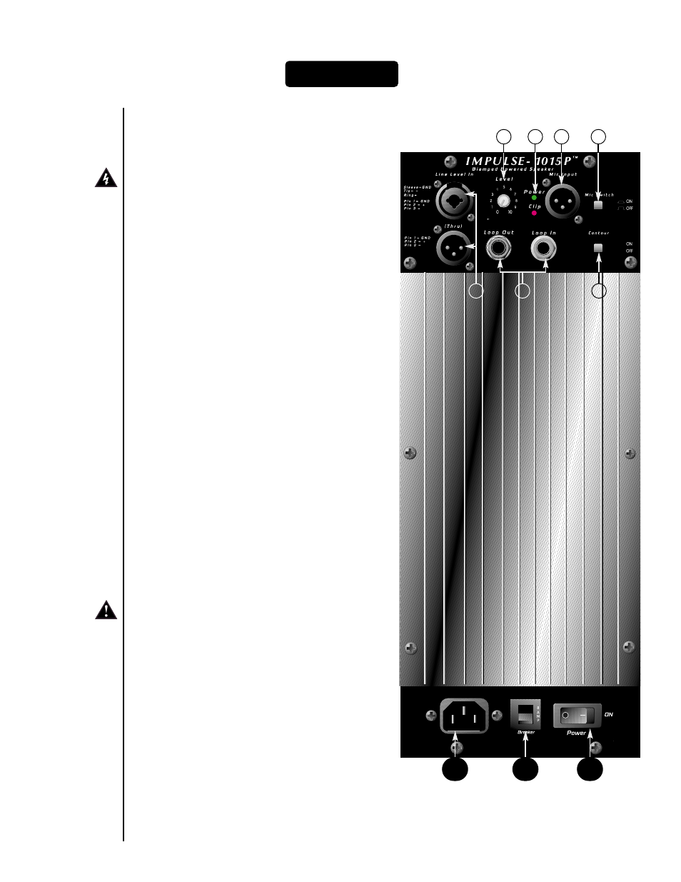
The unit is AC power line circuit breaker-
protected from overloads and fault conditions
with a resettable 8 Amp breaker. In the rare event
this unit should trip the breaker, turn the power
switch to the OFF position, reset the breaker by
pushing the center lever in all the way and
reactivate the power switch. If the breaker lever
does not stay in, it may need to cool first.
If the unit trips the breaker again and again, DO
NOT continue to resetting the breaker, have the
unit checked by a qualified service technician.
((2
2)) IIE
EC
C P
PO
OW
WE
ER
R C
CO
OR
RD
D C
CO
ON
NN
NE
EC
CT
TIIO
ON
N
The removable AC power cord plugs into this
socket to supply AC line voltage to the power
switch.
((3
3)) O
ON
N--O
OF
FF
F S
SW
WIIT
TC
CH
H
This switch supplies AC power to the system
electronics when switched to the ON position.
((4
4)) P
PO
OW
WE
ER
R L
LE
ED
D
Illuminates when the preamp electronics receive
power, and should illuminate when the power
switch is in the ON position and the AC power
cord is connected and plugged into the wall
outlet.
((5
5)) P
PR
RIIM
MA
AR
RY
Y IIN
NP
PU
UT
TS
S/
/O
OU
UT
TP
PU
UT
TS
S
The input and output jacks are in parallel to allow
the audio input signal to be daisy-chained to
other devices. The “input” level is the same as
the “output” level and there is no isolation
between the various jacks. Input jack (5a) is a
medium impedence balanced combo female XLR
and 1/4" RTS connector, while jack (5b) is a male
XLR.
((6
6)) V
VO
OL
LU
UM
ME
E
This controls the gain (level) of the Impulse 1015P
system. When used with the Primary Input
/Output jacks (5), it directly sets the system
output level. If the microphone input is utilized in
conjunction with the Primary In/Out jacks, then
R
Re
ea
arr P
Pa
an
ne
ell
6
2
3
1
4
8
7
5
10
9