Receiving, Installation & assembly – Powermatic 31A User Manual
Page 8
8
RECEIVING
Remove the sander and base and any loose parts from
their containers. Check for damage and ensure all parts
are intact. Any damage should be reported to your
distributor and shipping agent immediately upon
discovery. Before proceeding with assembly, read the
manual thoroughly; familiarize yourself with correct
assembly and maintenance procedures and proper
safety precautions.
Contents of crate:
1 base assembly with motor
1 sander body
1 abrasive belt
1 abrasive disc
1 fence assembly
1 hardware bag
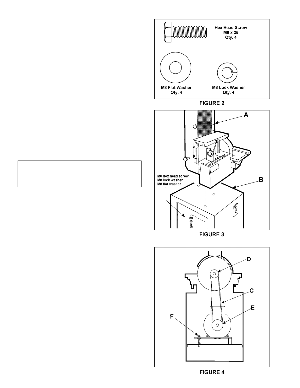
The contents of the hardware bag are drawn in Figure 2.
INSTALLATION & ASSEMBLY
Tools required
adjustable wrench (or socket wrench set)
hex wrenches
1. If the machine is to be secured to the floor, use
high quality lag screws through the four holes inside the
bottom of the base. If using a mobile base, be sure to
lock the wheels before assembling, operating or making
adjustments to the sander. (A mobile base for your
sander is available from Powermatic – stock # 708221.)
2. Mount the sander body (A) to the stand (B) with
four M8 x 25 hex head screws, four M8 lock washers
and four M8 flat washers as shown in Figure 3.
3. The drive belt (C) is already mounted on the drive
sheave (D) behind the disc, as shown in Figure 4.
However, it should be checked to ensure that it is in the
sheave groove.
4. Position the belt (C) around the motor sheave (E)
and tension the belt by adjusting the nuts (F) on the
tensioning screw.
NOTE: Proper tension is achieved when there is
moderate deflection in the belt midway between the two
sheaves.
ELECTRICAL CONNECTIONS
Wire the sander in accordance with the requirements of
the National Electrical Code (ANSI/NFPA70). See wiring
diagram on pages 20-21. Make sure your power source
matches the rating on the machine’s motor nameplate.