Technical data – Philips TL24A5T User Manual
Page 17
17
Technical data
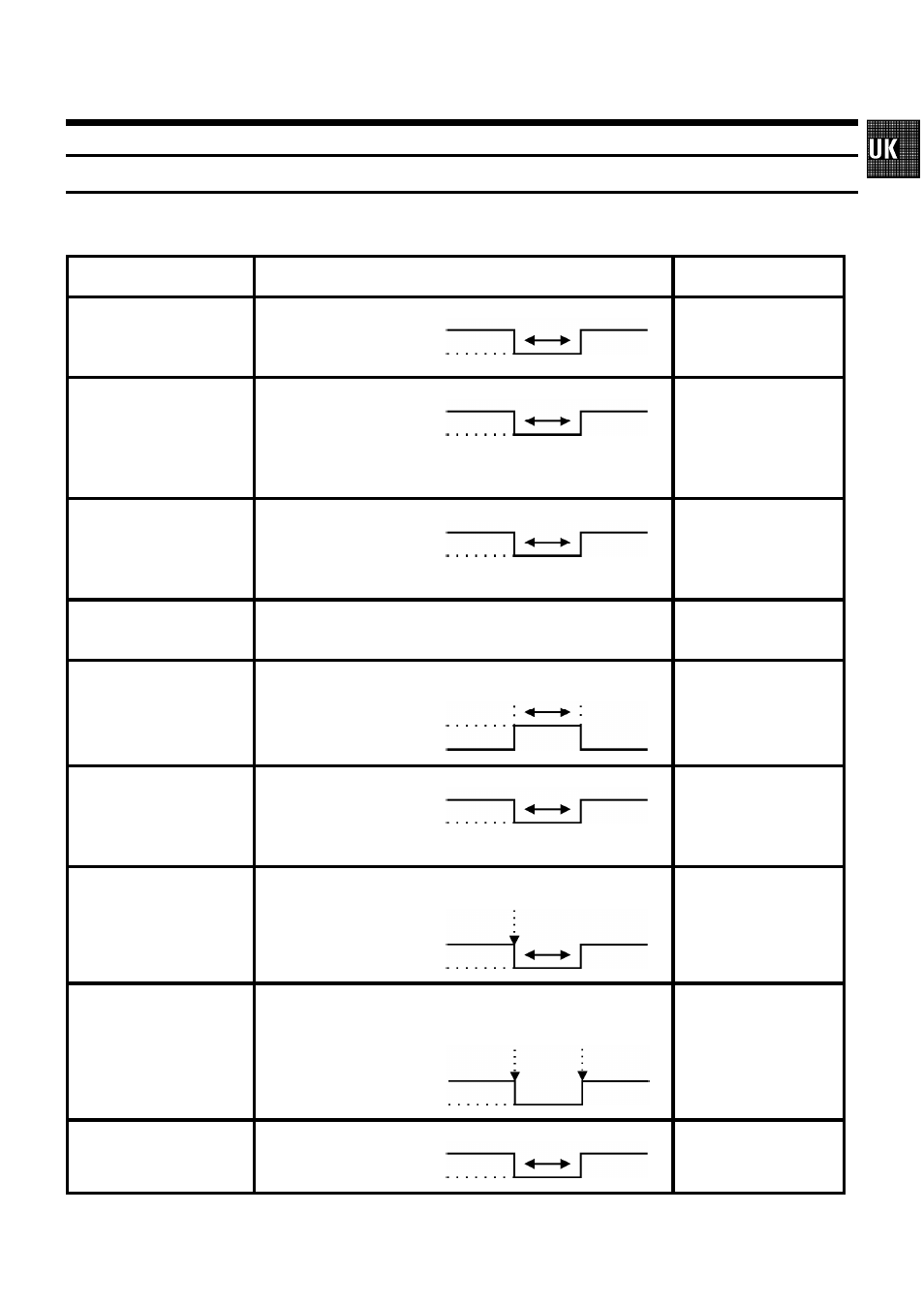
Signallevel on control socket
Connection
Signallevel
Note
Pin 1
ALARM IN
Alarm input
HIGH: 5V
LOW: GND
min. 0,5 sec.
Input active with LOW
signal level
Pin 2
SERIAL IN
Starting the recording
on a second video
recording
HIGH: 5V - 12V
LOW: GND
min. 0,5 sec.
Input active with LOW
signal level
Pin 3
RESET/REC OUT
Alarmreset
HIGH: 5V
LOW: GND
min. 0,5 sec.
Input active with LOW
signal level
Output active with HIGH
signal level
Pin 4
GND
Mass
Pin 5
ALARM OUT
Alarm output
HIGH: 12V
Iout = max. 50mA
Short circuit protected
Setting the menu in ALARM
SETTINGS
Output active with HIGH
signal level
Pin 6
SERIAL OUT
Output for starting a
second video recorder
HIGH: 12V
Iout = max. 50mA
Short circuit protected
10 sec.
Output active with LOW
signal level
Pin 7
CAMERA SW OUT
Camera switching pulse
HIGH: 5V
LOW: max. 0,8V
Internal pullup 5kOhm
4 frames after the recorded
frame
Output active with LOW
signal level
Pin 8
TAPE END OUT
Tape end warning
HIGH: min. 11V
Iout = max. 50mA
Short circuit protected
15 Minutes be-
fore end of tape
EJECT or
REWIND
Output active with LOW
signal level
Pin 9
RECORD CHECK
HIGH: 5V - 12V
LOW: GND
at least 0,5 sec.
Input active with LOW
signal level