Start / stop switch, Electrical connection, Adjustments – Powermatic PJ1696 User Manual
Page 11: Drive belt
11
START / STOP SWITCH
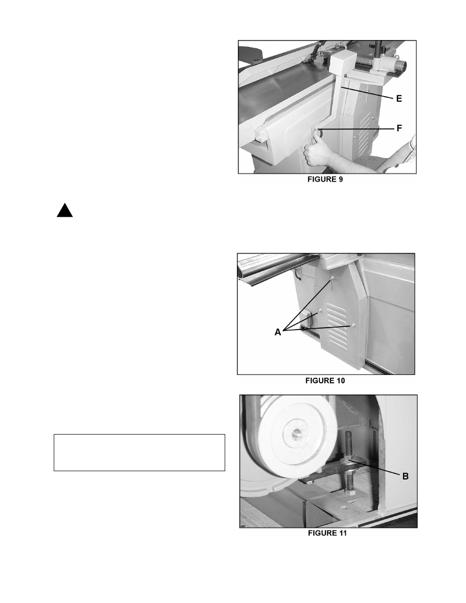
The arm (E-Fig. 9) on which the pushbutton
switch is located is shipped in the down
position. The screws (F-Fig. 9) should be
loosened with a 10mm hex wrench and the
arm pivoted to upright position. Re-tighten
screws.
ELECTRICAL CONNECTION
IMPORTANT: Make sure the electrical
characteristics are the same between the
motor nameplate and the power source, and
make sure the circuit on which the jointer will
be used is properly fused and that the wire
size is correct.
WARNING: Electrical connections
must be made by a qualified
electrician. The machine must be
properly grounded to help avoid
electric shock and possible death.
1.
Connect wires both to junction box and
power source (see electrical schematic, page
34). The green wire (ground) must be
properly grounded.
2.
After wiring is complete, turn motor on
momentarily to check for proper direction of
rotation (cutterhead should rotate toward
infeed table). If rotation is in the wrong
direction, disconnect machine and switch any
two of the hot leads. Reconnect power and
confirm proper rotation.
3.
Run the machine without cutting for a
short time to check that all powered functions
are operating properly.
ADJUSTMENTS
Tools required
17mm & 19mm spanner
DRIVE BELT
Remove the three crown nuts and washers
(A-Fig. 10) on the belt cover with a 17mm
spanner, and remove the cover. Use a
19mm spanner to adjust the nuts in the motor
support (B-Fig. 11).
!