St sma – Patton electronic 1140 User Manual
Page 5
S2-3: Extended Signaling Rate
The setting for switch S2-3 determines the range of variability the
Model 1140 “looks for” in asynchronous data rates (i.e., the actual vari-
ance from a given frequency level the Model 1140 will tolerate).
S2-3
Setting
Off
-2.5% to +1% Basic
On
-2.5% to +2.3% Extended
S2-4 and S2-5: RTS/CTS Delay
The combined settings for switches S2-4 and S2-5 determine the
amount of delay between the time the Model 1140 “sees” RTS and
when it sends CTS. Options are no delay, 7 ms and 53 ms.
S2-4
S2-5
Setting
On
On
7 mS
Off
On
53 mS
On
Off
No delay
Off
Off
No delay
S2-8: V.54 Loopback Test Enable
To reset the V.54 circuit, set switch S2-6 to the “ON” position, then
back to the “OFF” position..
S2-8
Setting
Off
V.54 Enable
On
V.54 Disable
4.0 INSTA L L AT I O N
The Model 1140 is easy to install. After configuring the DIP
switches, simply connect the two fiber cables and then connect the
RS-232 interface. Figure 5 shows the location of the fiber connections
on the Model 1140’s rear panel.
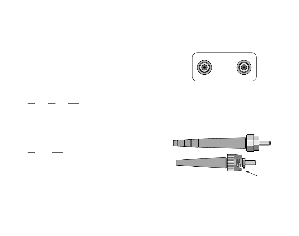
4.1 FIBER CONNECTIONS
The Model 1140 short range modems are designed to work in
pairs
. You will need one at each end of a dual fiber cable. This cable
connects to each Model 1140 using either an ST or an SMA connector.
Figure 6 shows a close up of each of these connector types.
4.2 RS-232 CONNECTION
The Model 1140 is designed to remain in DCE mode.
Figure 6. Close up of ST and SMA connections
Figure 5 Close up of ST and SMA connections
ST
SMA
Alignment pin
faces down
Fiber
Fiber
7
8