Patton electronic 2135 User Manual
Page 7
11
APPENDIX A
PATTON ELECTRONICS MODEL 2135
SPECIFICATIONS
LAN Connection: RJ-45, 10BaseT, 802.3 Ethernet sup-
ported by Transparent LAN bridging
DTE connection:
M34 connector, V.35 (DTE orientation).
Protocol:
PPP (RFC 1661) with Bridging Control
Protocol (RFC 1638)
MAC Address
Table Size:
4096 entries
MAC Address Aging: MAC addresses deleted after eight min-
utes inactivity
On-board Memory:
512 KB RAM; 128 KB FLASH
Frame Latency:
1 frame
LEDs LAN Side:
(1) yellow, general status; (1) green,
link integrity
LEDs DTE Side: TD, RD and Power, (green); DTR,
CTS and CLK, (Yellow)
Power supply Input:
100-240VAC, 50-60Hz, 0.4A
Power Consumption:
500mA @ 5VDC.
Humidity:
Up to 90% non-condensing
Temperature:
0 -50 C
Dimensions:
9.0 x 5.3 x 2.0 cm (3.5"L x 2.1"W x
0.78"H)
Compliance:
FCC Part 15A
CE Mark per EEC Directive
89/336/EEC
Low Voltage Directive
73/23/EEC
TXD- Trasmit data LED (green) blinks to indicate data transitions
and remains OFF when no data is transmitted (idle).
RXD- Received data LED (green) blinks to indicate data transi-
tions and remains OFF when no data is received (idle).
DTR- Data Terminal Ready LED (yellow)- turns ON at power up
to indicate to the DCE that the 2135 is active.
CTS- Clear to Send LED (yellow) - turns ON when the 2135 is
ready to receive data from the DCE.
DCD- Data Carrier Detect LED (yellow) - Turns ON to indicate
that a carrier detect signal is received from the DCE.
CLK- Clock Signal LED (yellow) - blinks to indicate that the
transmit clock from the DCE is active. The CLK LED will remain
OFF to indicate the absence of the transmit clock.
PWR- LED (green) turns ON as soon as power is applied to the
2135.
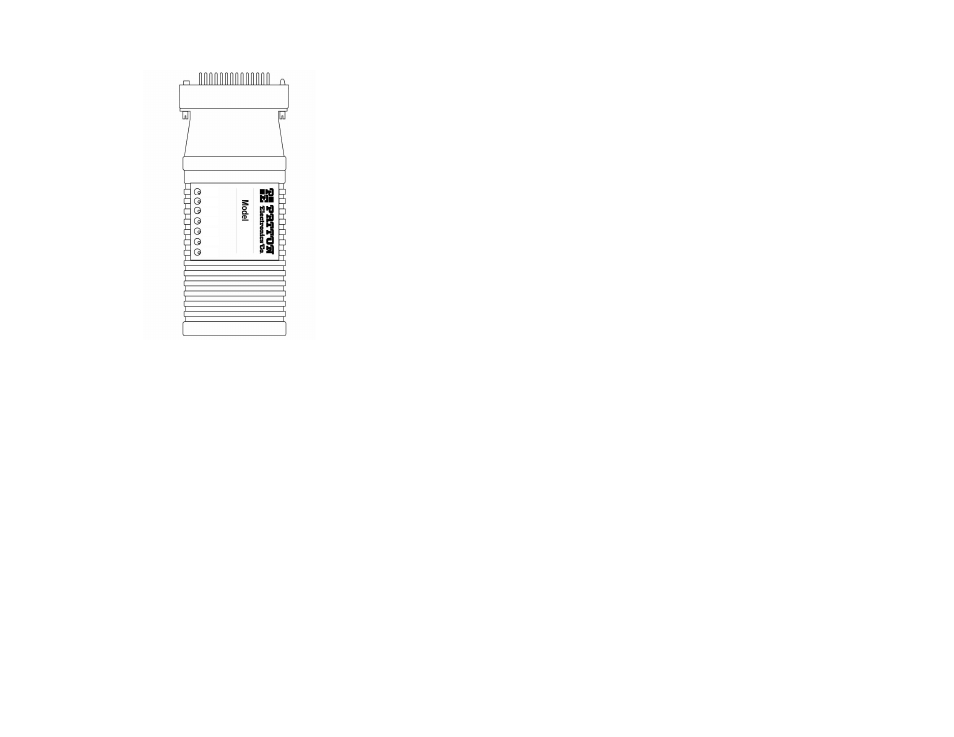
Figure 5. Front of Model 2135, showing LED Indicators
12
2135
TXD
RXD
CTS
DTR
DCD
CLK
PWR