Patton electronic 1015S User Manual
Page 6
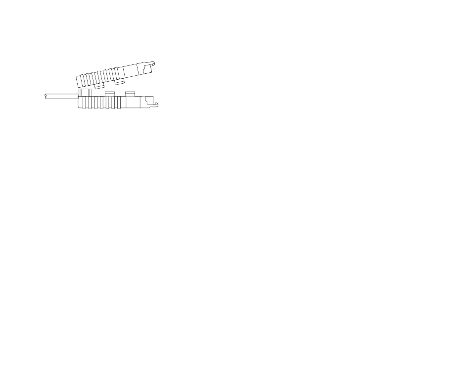
10. TIP the top half of the case as necessary to place it over the
strain relief assembly. Do not snap the case together yet.
11. Insert one captive screw through a saddle washer and then
insert the entire piece through the hole in the DB-15 end of the case.
Snap that side of the case closed. Repeat the process for the other
side. This completes cable installation.
4.2 CONNECTION TO THE RS-232 INTERFACE
Once you have configured the Model 1015 for DTE or DCE and
connected the twisted pair wires correctly, simply plug the 1015 directly
into the DB-15 port of the RS-232 device. After doing so, remember to
insert and tighten the two captive connector screws.
Note: If you must use a cable to connect the Model 1015 to the
RS-232, make sure it is a
straight through
cable of the shortest possi-
ble length—we recommend 6 feet or less. The Model 1015 requires a
cable that incorporates pins 1, 2, 3, 4, 9, 10, 11 and 12.
4.3 OPERATING THE MODEL 1015
Once the Model 1015 is properly installed, it should operate trans-
parently—as if it were a standard cable connection. Operating power
is derived from the RS-232 data and control signals; there is no
“ON/OFF” switch. All data signals from the RS-232 interface are
passed straight through. All control signals from the RS-232 interface
are looped back.
Note: If your system requires
hardware
flow control, you will need
the Patton Model 1012 or Model 1060 Short Range Modem. Call
Patton Customer Service at (301) 975-1007 for more information.
APPENDIX A
PATTON MOCEL 1015 SPECIFICATIONS
Transmission Format: Asynchronous
Data Rate:
0 to 19,200 bps (no strapping)
Surge Protection:
600W peak power dissipation at 1 mS
(10 x 1000 µs exponential waveform) and
response time of 1.0 pS
Control Signal:
CTS (Pin 10) turns ON immediately after
the terminal raises RTS (Pin 2); DSR (Pin 3)
turns on when powered up; DCD (Pin 12)
turns on immediately after the terminal
raises DTR (Pin 4)
Transmit Line:
4 wire, unconditioned line (2 twisted pairs)
Transmit Mode:
Full duplex, 4-wire
Transmit Level:
0
dBm
Line Connection:
RJ-11 or RJ-45 jack or 5 screw terminal
posts (4 wires and 1 ground) and a strain
relief insert
Power Supply:
No external power required, uses ultra low
power from EIA data and control signals
Size:
2.6” x 1.3” x 0.75”
9
10