Figure 4-4 components on an rpu, Figure 4-5 components on an npu board – Panasonic 324566-A User Manual
Page 67
Nortel Secure Router 8012
Hardware Description
4 Boards
Issue 5.3 (6 April 2009)
Nortel Networks Inc.
4-9
Do not let your eyes near or stare at the optical interface or the fiber interface. The laser beam
is harmful to your eyes.
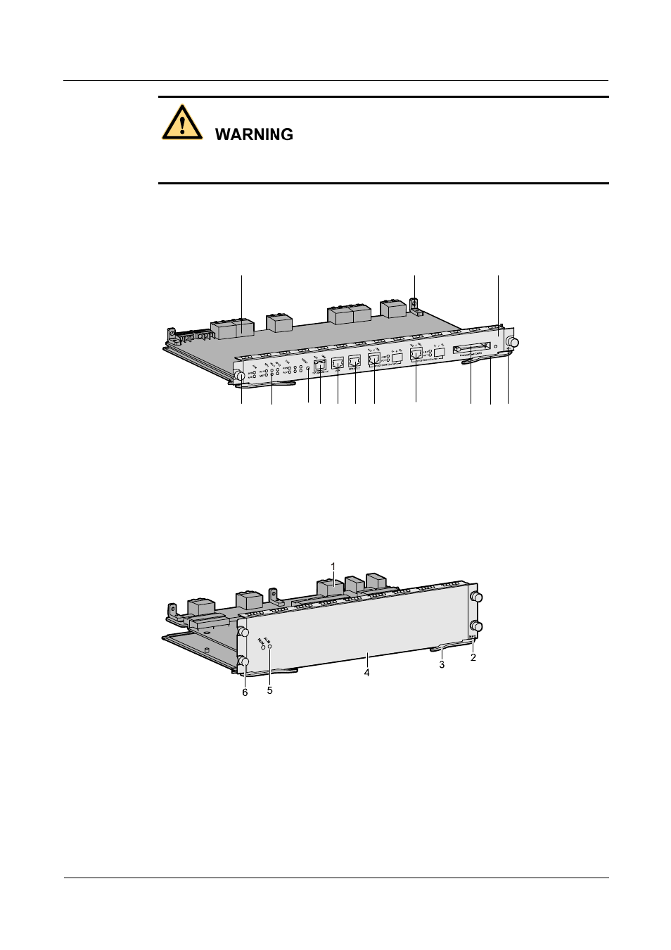
Figure 4-4, Figure 4-5, and Figure 4-6 show the appearance of the RPU, NPU, and HIC/FIC,
using the the 8FE as an example.
Figure 4-4 Components on an RPU
PW
R1
PW
R2
1
2
3
4
5
6
7
7
8
10
12
13
9
11
1. Connector
2.Guiding jack
3.Board
4.Board silkscreen
5. Handle
6. Reserved interface
7. 100/1000M Ethernet interface
8. CONSOLE port
9. AUX port
10. 10/100/1000M Ethernet interface
11. Reset key
12. Indicator
13. Captive screw
Figure 4-5 Components on an NPU board
1. Connector
2. Board silkscreen
3. Handle
4. Board
5. Indicator
6. Captive screw