A.1.3 hic/fic indicators, A.2 fan module indicators, A.3 power module indicators – Panasonic 324566-A User Manual
Page 144: Table a-3 hic/fic indicators, Table a-4 indicators of the fan module, Table a-5 indicators of the power module
Nortel Secure Router 8012
Hardware Description
A List of indicators
Issue 5.3 (6 April 2009)
Nortel Networks Inc.
A-3
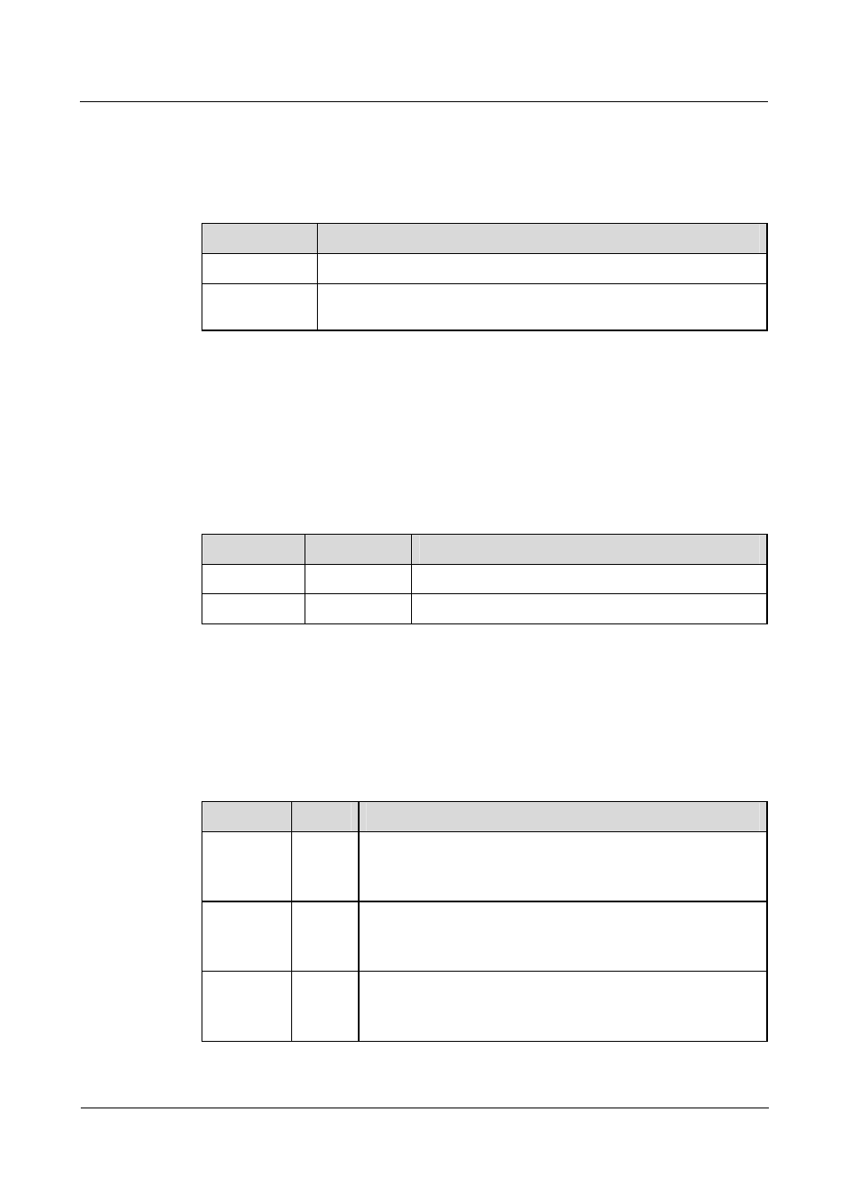
A.1.3 HIC/FIC indicators
Table A-3 shows the status and description of HIC/FIC indicators.
Table A-3 HIC/FIC indicators
Name
Description
LINK (Green)
OFF means the link is not connected and ON means the link is connected.
ACT (Yellow)
OFF means no data is being transmitted or received on the interface and
blinking means data is being transmitted or received.
A.2 Fan module indicators
The indicators of the fan module are located on the RPU front panel. Table A-4 shows the
status and description of the indicators.
Table A-4 Indicators of the fan module
Name
Color
Description
RUN
Green
Constant ON means the fan is operating normally.
ALM
Red
ON means the FAN has failed.
A.3 Power module indicators
Table A-5 shows the status and description of the power module indicators.
Table A-5 Indicators of the power module
Name
Color
Implication
AC OK
Green
The power module input LED (only for the AC power module).
Constant ON means the voltage input is normal (100 V to 240 V),
and OFF means the voltage input is not normal.
DC OK
Green
The power module input LED (only for the DC power module).
Constant ON means the voltage input is normal (-48 V to -60 V),
and OFF means the voltage input is not normal.
RUN
Green
The power module indicators.
Constant ON means the power module runs normally, and OFF
means the power module has faults.