C. dip switch & jumper settings, On control board in display head, On i/o board in base – POSIFLEX Business Machines LCD Customer Display PD-7100 User Manual
Page 12
3 - 5
C. Dip Switch & Jumper Settings
1. On control board in display head
Emulation mode (reach the switches from outside of back of the head)
SW2
SW1
OFF ON
OFF
EPSON 2 X 20
NORITAKE 2 X 20
ON
EPSON 4 X 26
IEE (CHINESE) 2 X 10
RS232 protocol (Inside display head)
Short
Open
JP1
19200, n, 8, 1
9600, n, 8, 1 (default)
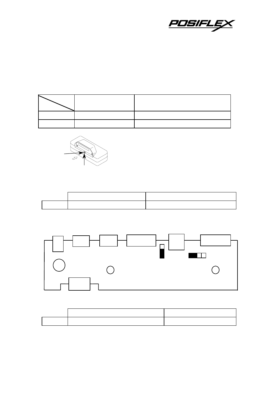
2. On I/O board in base
Board layout
Posiflex POS system power supply:
1 – 2 Short
3 –4 Short
JP1
+12 V DC for PST series (default)
+5 V DC for TP series
Hardware handshaking control:
Push up to
switch on
SW1
SW2
RS232 Out
CN1
P4
J1
S1
P1
RS232 In
1
4
JP1
1
JP2
This manual is related to the following products: