Installation – Philips LTC 3963/51 User Manual
Page 10
9
PHILIPS LTC3963/51 (E) QR31809
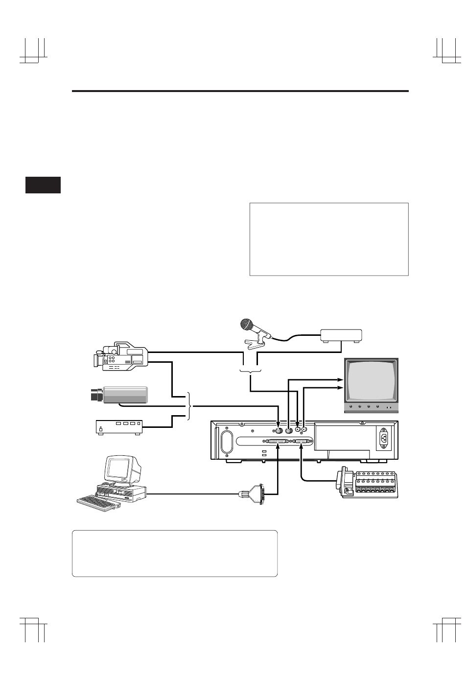
15-PIN ADAPTER (provided)
*
It is necessary to connect
to suit your purpose.
SWITCHER
PERSONAL COMPUTER
(with RS-232C jack)
RS-232C reverse type cable
VIDEO CAMERA/RECORDER
PREAMP
MICROPHONE
CAMERA
MONITOR
INSTALLATION
VIDEO CONNECTIONS
Use coaxial cables when connecting a camera and a
monitor to this VCR.
Note: Long cable runs to distant cameras may
cause signal deterioration and/or sync discrep-
ancies. If these problems occur, use video line
amplifiers and/or cameras having phase-adjustable
line-locked vertical sync.
Video Input
In single camera systems, connect the camera to the
Video IN BNC terminal on the VCR rear panel. Use
of a 2:1 interlace camera is highly recommended;
otherwise, the monitor will show vertical distortion
of the TIME/DATE characters.
In multiple camera systems, connect the switcher
output to the Video IN BNC terminal. Because mul-
tiple camera systems require synchronization, use
of cameras having line-locked vertical sync or a gen-
locked master drive/sync source is highly re-
commended. The use of vertical interval switchers
is also recommended.
Video Output
Connect the monitor to the Video OUT BNC terminal
on the rear panel.
AUDIO CONNECTIONS
Note: Audio recording can be performed at the 09
and 27-hour recording speeds and audio playback at
the 09 and 27 speeds.
Audio In: Accepts an audio signal from a camera,
external sound equipment, or another recorder
(Line: –8 dBm, 50 kohm).
Audio Out: Provides an audio output for a monitor
or another recorder (–9 dBm, 600 ohm, unbalanced).
USING THE 15-PIN ADAPTER
Attach the wires of the alarm switch, door sen-
sor or warning lamp to the 15-pin adapter
using screws.
After connection, connect the adapter to the
EXTERNAL INTERFACE jack on the rear of the
VCR.
See pages 10 and 11 for details.
Functions of RS-232C Connector Pins
1. Ground
2. Data transmission
3. Data reception
4. Connected to pin 5.
6. Connected to pin 20.
7. Ground
8 ~ 19 and 21 ~ 25. Not connected.
Note: The RS-232C is a standard
null-modem cable that can be
purchased locally.