Proceed to step 11, And screws for later reinstallation. see figure 4 – Powerware 208/120V User Manual
Page 18
INSTALLATION
EATON Powerware
®
Energy Management System (EMS) Upgrade Kit User’s Guide
S
164201724 Rev 1
www.powerware.com
12
8.
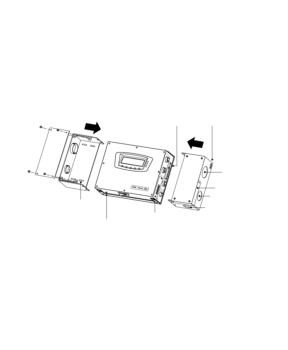
If installing a right conduit box, connect the DB−9 extender cable
(installed on the extended serial port on the inside of the right
conduit box) to the serial port (Service) on the electronics module.
Figure 4 shows the location of the two serial ports.
9.
Slide the conduit box into place on one side of the electronics
module. Loosen the mounting bracket screws further if needed.
If installing conduit on both panels, repeat for the other conduit box.
Tighten the mounting bracket screws to secure the conduit box(es).
Left Conduit
Box
Front
Plate
Front
Plate
Mounting
Slots
(4 places)
Serial Port
(Service)
Extended
Serial Port
Card Cover Plate
Mounting Bracket
Screws (8 places)
Ground Bonding Screw
2" Bushing
1.5" Bushing
1" Bushing
Right Conduit Box
Figure 4. Conduit Box Option
10. Optional but recommended. Attach the conduit box(es) to the wall
with appropriate wall anchors (not supplied). Use one or more of
the four available mounting slots in each conduit box.
11. Verify that all hardware is mounted and aligned properly, then
tighten all screws. Verify the hardware is attached safely and
securely to the wall.
12. Continue to the following section, Electrical Connections."