Powerware 208/120V User Manual
Page 29
INSTALLATION
EATON Powerware
®
Energy Management System (EMS) Upgrade Kit User’s Guide
S
164201724 Rev 1
www.powerware.com
23
NOTE Use wire taps ONLY on thermoplastic insulation (PVC).
14. Occupied three−phase branch circuit breaker connection only. Verify that
the branch circuit breaker is turned off. Be absolutely certain there
is no power.
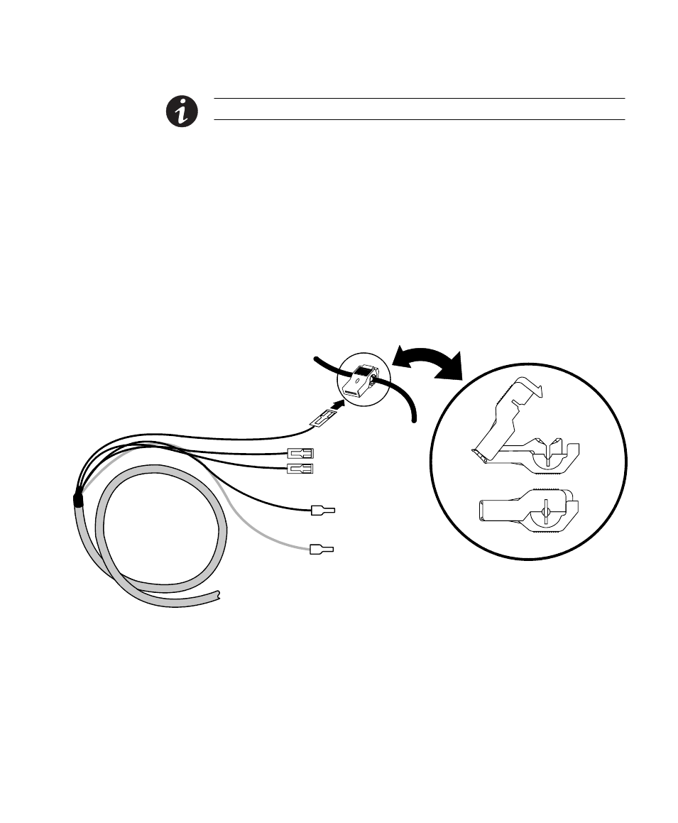
Use pliers to carefully install the appropriate size wire taps
(supplied) to phase A, B, and C wiring on the occupied circuit
breaker. See Figure 12. For sizing, see Table 3 on page 14.
Verify the wire taps are completely closed around the wires.
Connect the phase A, B, and C connectors on the voltage harness
to the appropriate installed wire taps. Coil and secure any excess
cable away from other conductors.
Wire Tap
A, B, C
Phases
Ground
Neutral
Voltage
Harness
Wiring to Occupied Breaker
Figure 12. Voltage Harness Connections to Occupied Breaker (V1 Harness Shown)
15. If installing dual panels, repeat Steps 11 through 14 for the voltage
harness V2 and Panel 2 for Neutral, A, B, and C phase connections.
Panel 2 does not have a Ground connection.
16. Verify all installed voltage monitoring wiring is correct and follows
NEC and local guidelines.