Phoenix Gold pm700 User Manual
Page 13
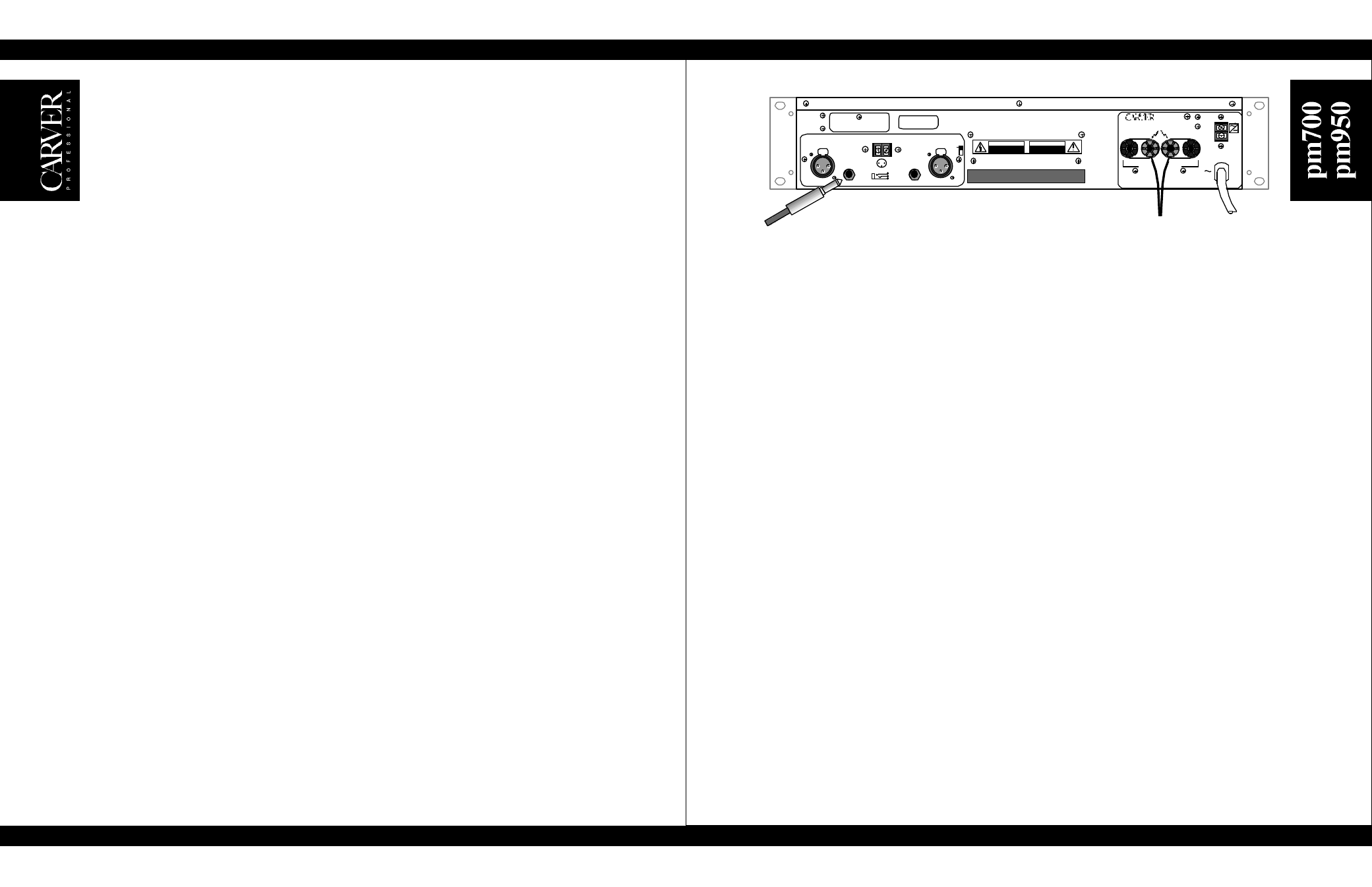
Output Wiring
Use heavy gauge wire for speaker connections. The greater the distance between the amplifier and
the speakers, the larger the diameter the wire should be to minimize power losses across the wire
and improve the damping of the speaker. Wire thickness specifications (or gauges) get larger as
the wire gets thinner; thus 14-gauge wire is thicker than 16-gauge wire. Use the following as a
guide: up to 25 ft. use 16 gauge, up to 40 ft. use 14 gauge, up to 60 ft. use 12 gauge, up to 100 ft.
use 10 gauge, up to 150 ft. use 8 gauge, up to 250 ft. use 6 gauge.
This will insure that the resistance of the speaker wire is less than 5% of 4 ohms, resulting in a transmission
loss of less than 0.5 dB. The multi-way binding posts can accept spade lug, bare wire or banana connections.
Be sure that all the fine strands of the wire are twisted together and contained within the connector. If even
one strand is loose and can touch the adjacent terminal, a short circuit may result. Class I (NEC) wiring must
be used.
Polarity
Loudspeakers must be connected with consistent polarity for correct phasing between them. Incorrect
phasing will do no physical harm, but frequency response will be affected. The key is to make sure that both
speakers connected to the speaker terminals are hooked up the same way. Connect (–) at the speaker outputs
to (–) on the back of the speaker, and (+) at the speaker outputs to (+) on the back of the speaker.
Dual Mono
The Stereo/Mono switch is located on the Input Board which is connected to the input panel. Connect the input
signal to CH2 input (CH1 input becomes disabled). Connect the speakers to the Speaker Outputs on the
amplifier in the same way that you would for normal stereo operation. Both speaker outputs will carry the signal
that is connected to the CH2 input.
Bridged Mono
The Stereo / Mono switch is located on the Input Board which is connected to the input panel. Connect the
input signal to CH2 input (CH1 input becomes disabled). Connect the speaker(s) to the two (+) speaker
terminals. The CH2 (+) terminal is the hot (non-inverting) side, and the CH1 (+) terminal is the low (–,
inverting) side. When connected in this way, each channel “sees” one-half the impedance of the speaker that
is connected between them. If an 8 ohm speaker is used, each channel will see a 4 ohm load. Therefore it is
not recommended that any load lower than 8 ohms be connected in this mode of operation. Use Parallel
Mono operation for lower impedances. Note: Be sure to set both of the input level controls to the exact same
setting for equal power distribution per channel. Switching the Level Defeat Switch off is a handy way to
insure that both channels are operating at the same level.
CAUTION: In bridged mono operation, the output connections are actually a balanced output
configuration. This means that both output terminals have voltage present (neither one may be grounded).
Parallel Mono
Parallel-mono operation is useful when you are running sustained high levels into a single load, or when driving
a low impedance load. To configure the amplifier for parallel-mono operation, contact Carver Technical Service
Department for Field Application Bulletin pm700-1. It contains detailed instructions describing the simple
procedure for modifying both the pm700 and pm950 power amplifiers for parallel-mono operation.
10
11