Warning – Patton electronic 2703 User Manual
Page 7
Jumper LK6 & LK7: 75 Ohm Termination Impedance
This jumper sets the termination impedance correctly for 75 Ohm
operation. Both jumpers must be in place when operating in 75 Ohm
(unbalanced) mode. Conversely, both jumpers must be removed when
operating in 120 Ohm (balanced) mode.
LK6
LK7
Setting
On
On
75 ohm operation
Off
Off
120 ohm operation
3.3 POWER SUPPLY OPTIONS
The Model 2703 is available with three power supply options:
The
Standard
power supply option (Model 2703 or 2703-230) is
factory configured for either 115 or 230 VAC, depending on how
the product is ordered, and is available with a variety of domestic
and international power cords (see Appendix C).
The
Universal Interface
power supply option (Model 2703-UI)
operates in environments ranging from 85 to 265 VAC, with no re-
configuration necessary (see Appendix C for available domestic
and international power cords).
The
DC
power supply option (Model 2703-DC) operates in 48
VDC environments and is equipped with a 3-pin “terminal strip”
style DC power cord.
11
WARNING!
There are no user-serviceable parts in the
power supply section of the Model 2703. Voltage setting
changes and fuse replacement should only be performed
by qualified service personnel. Contact Patton Electronics
Technical support at: http://www.patton.com; or, sup-
[email protected](301)975-1007 for more information.
4.0 INSTALLATION
Once the Model 2703 is properly configured, it is ready to connect
to your system. This section tells you how to properly connect the
Model 2703 to the G.703 network and terminal device interfaces.
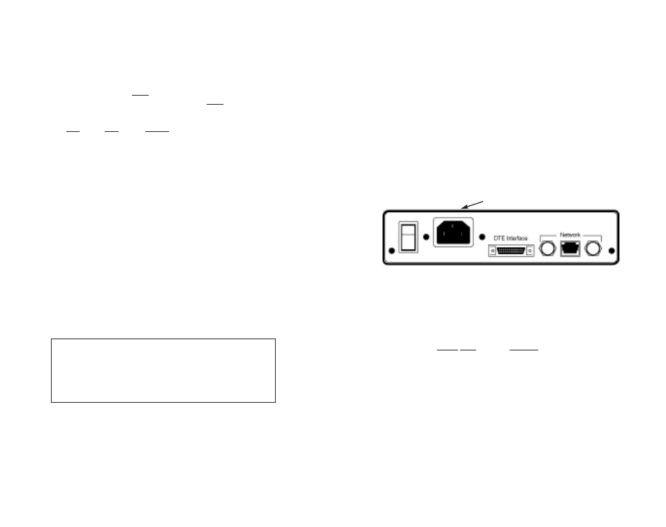
4.1 CONNECTION TO THE G.703 NETWORK
The Model 2703 supports 2.048 Mbps communication over an
unstructured G.703 network. Both 120 ohm twisted pair and 75 ohm
coax interfaces are provided on the rear panel of the Model 2703 (see
Figure 5, below). Be sure the unit is configured properly to operate in
either 120 ohm or 75 ohm mode, and that the network connection is
grounded appropriately (see Section 3.0).
4.1.1 TWISTED PAIR (120 OHM) CONNECTION
The Model 2703 is equipped with a single RJ-45 jack for connec-
tion to a 120 ohm twisted pair G.703 network interface. The pinout of
this jack is as follows:
RJ-45 Pins
SIGNAL
1 & 2 . . . . . . . . . . . . Receive pair (from network)
3 . . . . . . . . . . . . . . . Shield reference point
4 & 5 . . . . . . . . . . . . Transmit pair (to network)
6 . . . . . . . . . . . . . . . Shield reference point
7 . . . . . . . . . . . . . . . Not used
8 . . . . . . . . . . . . . . . Not used
4.1.2 DUAL COAX BNC (75 OHM) CONNECTION
In addition to the 120 ohm twisted pair connection, the Model 2703
is equipped with dual female BNCs (TX and RX) for connection to a 75
ohm dual coax G.703 network interface.
12
Figure 5. Model 2703 Rear Panel
(Model 2703-DC has terminal strip)