Equipment grounding, Led indicators, Factory test straps – Patton electronic 2020P User Manual
Page 6
147001UA
2-2
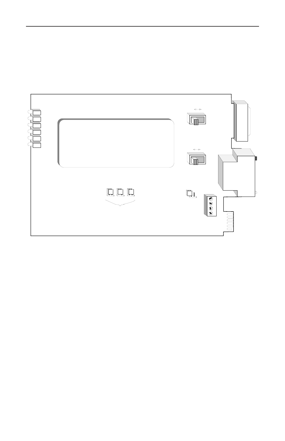
To connect a V.35 terminal type device (DTE) to an RS-232 Modem type
device (DCE), connect the terminal to J2 and the Modem to J1. Move
SW1 and SW2 to the DTE position, TOWARD THE FRONT OF THE
UNIT.
J1
JP3
JP2
J4
JP1
J2
JP4
CTS
Power
TD
DCD
RD
J3
SW2
SW1
RTS
V.24 INTERFACE
V.24 INTERFACE
DCE
DTE
4
3
2
1
DCE
DTE
Factory Test Straps
Must be Installed for Unit To
Operate Correctly
RS
-2
32
V.
35
J1 (RS-232) Is a DTE, and
MUST Connect to a Modem (DCE)
J2 (V.35)Is a DCE, and
MUST Connect to a Terminal (DTE)
Signal
to
Chassis
Ground
Equipment Grounding
JP4 provides grounding interconnection in those systems requiring a
connection between Pin # 1 (Frame Ground) and Pin # 7 (Signal
Ground). If signal ground and chassis ground interconnection is desired
install the jumper on JP4.
LED Indicators
The Following LED indicators are provided for diagnostics: Power,
Transmit Data (TD), Receive Data (RD), Request to Send (RTS), Clear
To Send (CTS) and Carrier Detect (DCD).
Factory Test Straps
The Factory Test Straps JP1, JP2 and JP3 must be installed for proper
operation of the 2020P (IC-V.24/V.35).