Solution series, Fully recessed architectural emergency lighting, Page 2 of 2 – Philips Lightolier Solution Series User Manual
Page 2: Job information type, Ordering information, Optics
Solution Series
Fully Recessed Architectural Emergency Lighting
Page 2 of 2
Philips Lightolier
e: [email protected]
t: (508)
679-8131
w: www.lightolier.com
Solution Series May 1, 2012
Specifications are subject to change without notice.
© Koninklijke Philips Electronics N.V., 2012. All rights reserved.
Job Information
Type:
Ordering Information
Series
SOL = Solution
Optics
* The optics layout shown is intended to be used as reference only. Standard reflectances used were 80/50/20. Lightolier is not responsible for site specific conditions that
may alter the results.
EX = Special Transformer (must specify voltage & frequency)
1
T = Self-Testing Diagnostics (non-audible)
TA = Audible Self-Testing Diagnostics
TD = Time Delay
2
TP = Tamperproof
Factory Installed Options
Accessories (order as a separate item)
SDREMOTE = Infrared Remote Test Device
IBHK = Bar Hanger Kit for Mechanical Ceilings
T15TPTOOL = Tamperproof Screwdriver
WMLK = Wall Mount Lens Kit
CMLKIT = Ceiling Mount Lens Kit
CMLKITB = Ceiling Mount Lens Kit for Black Unit
RPLTSW = Remote Test Switch Kit for Single Gang Wall Box 120 VAC
SOL
W = White
B = Black
Housing Color
Recessed Wall Mount Version, 7.5' AFF, Two Fixtures
Average initial footcandles at floor = 1.00
Minimum initial footcandles at floor = .3
Maximum initial footcandles at floor = 2.2
Maximum to minimum ratio = 7.33
7.5 ft.
WL = Wall Mount
CL = Ceiling Mount
Mounting
SD2 = Diagnostic
Electronics
Model Designator
SD2
Note
1) Some options impact UL listing. Consult factory for specifics.
2) 15 minute time delay.
2.0
2.2
2.1
1.5
2.0
2.1
2.0
1.5
1.9
2.0
1.9
1.5
1.7
1.8
1.8
1.4
1.5
1.6
1.6
1.3
1.2
1.4
1.4
1.2
1.2
1.2
1.3
1.2
1.2
1.2
1.2
1.1
1.2
1.2
1.2
1.2
1.0
1.1
1.2
1.1
0.8
0.9
1.0
1.0
0.6
0.8
0.9
0.7
.05
0.6
0.7
0.7
0.4
0.5
0.6
0.6
0.4
0.4
0.5
0.5
0.4
0.4
0.4
0.4
0.4
0.4
0.4
0.4
0.3
0.4
0.4
0.4
0.3
0.4
0.4
0.4
0.3
0.3
0.4
0.4
0.3
0.3
0.4
0.4
0.3
0.4
0.4
0.4
0.3
0.4
0.4
0.4
0.4
0.4
0.4
0.4
0.4
0.4
0.4
0.4
0.4
0.5
0.5
0.5
0.4
0.5
0.6
0.6
0.5
0.6
0.7
0.7
0.6
0.8
0.8
0.9
0.8
0.9
1.0
1.0
1.0
1.1
1.1
1.1
1.2
1.2
1.2
1.2
1.2
1.2
1.2
1.1
1.2
1.3
1.2
1.1
1.2
1.3
1.3
1.2
1.5
1.6
1.5
1.3
1.8
1.8
1.7
1.4
1.9
2.0
1.9
1.5
2.0
2.1
2.0
1.5
2.0
2.2
2.0
1.5
4 ft.
40 ft.
Recessed Ceiling Mount Version, 10' AFF, Two Fixtures
Average initial footcandles at floor = 1.07
Minimum initial footcandles at floor = .2
Maximum initial footcandles at floor = 4.8
Maximum to minimum ratio = 24.00
10 ft.
3.1
3.2
6 ft.
90 ft.
1.5
1.5
1.0
1.0
1.1
1.1
1.6
1.5
1.4
1.3
1.3
1.3
1.4
1.4
1.2
1.3
0.9
0.9
0.6
0.6
0.4
0.4
0.3
0.3
0.2
0.2
0.2
0.2
0.2
0.2
0.2
0.2
0.3
0.3
0.4
0.4
0.6
0.6
0.9
0.9
1.3
1.3
1.4
1.4
1.3
1.3
1.4
1.3
1.6
1.5
1.1
1.1
1.0
1.0
1.5
1.5
3.2
2.9
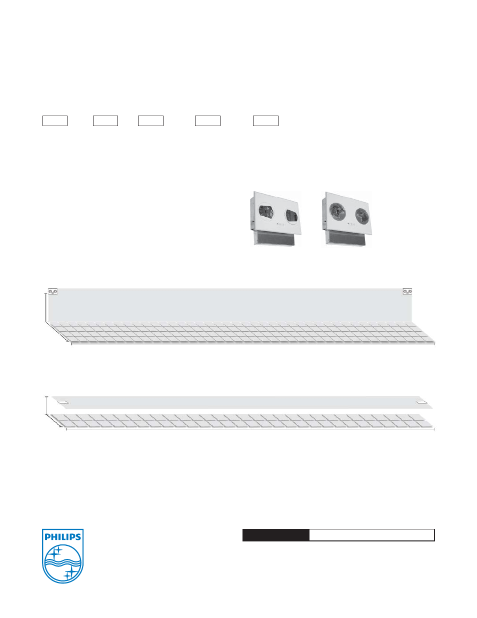
Ceiling version
before installation.
Wall version
before installation.
When using multiple fixtures, wall mounted versions can generate an average of 1 footcandle of emergency illumination over a 4’ x 40’ egress path, while ceiling mounted
versions can broadcast an average of 1 footcandle over a 6’ x 90’ egress path.