Analog connection, Rj-11 pinout diagram, Rj-11 socket – Patton electronic SmartNode 2294 User Manual
Page 27: Figure 9, Table 5, Rj-11, male, Rj-11, male pstn wall plate, Power console, Run v oip link link 100m activity
Installing the SmartNode extender
27
Model 2292 & 2294 Series Getting Started Guide
3 • Hardware installation
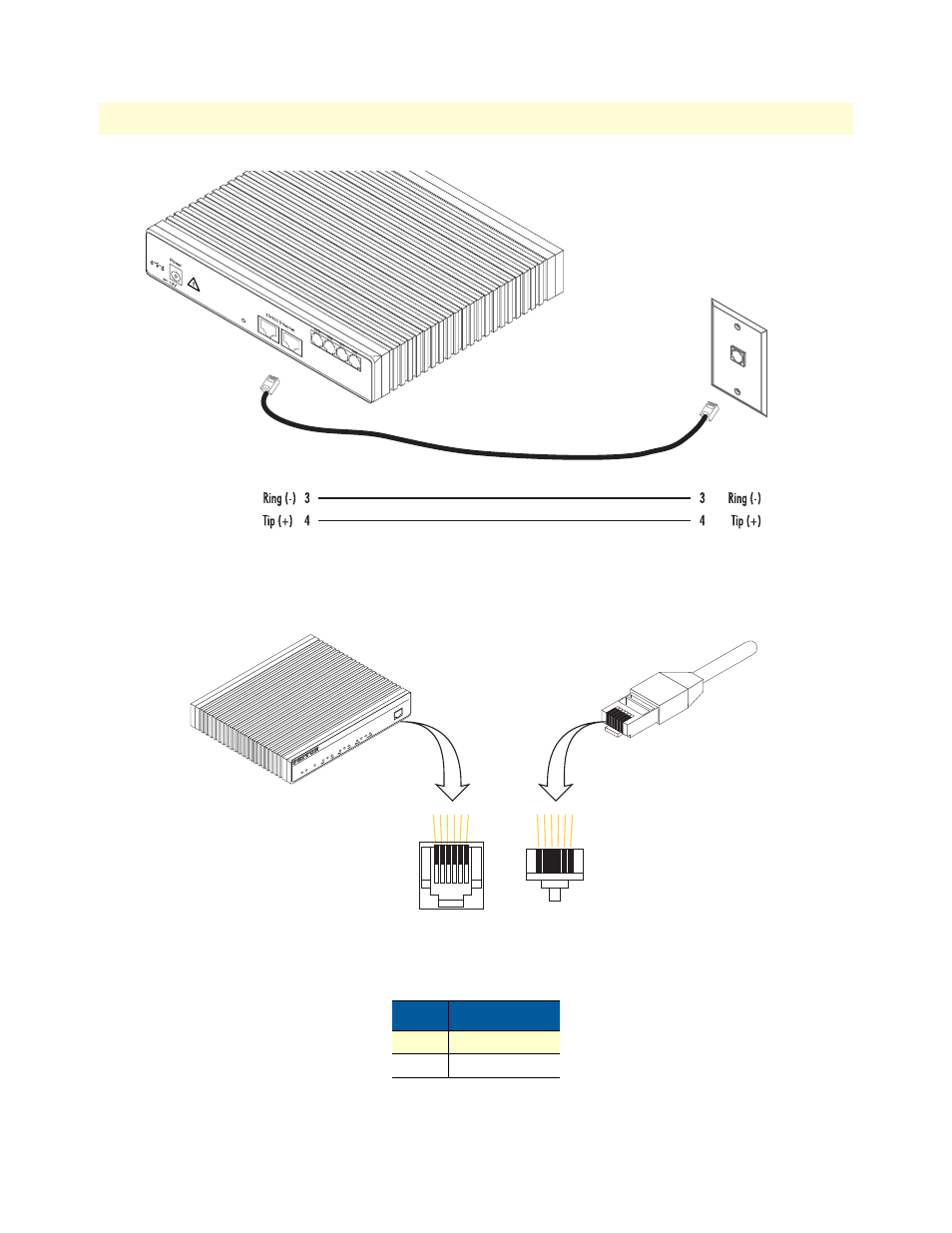
Figure 8. Analog connection
Figure 9. RJ-11 pinout diagram
Note
Unit must not connect directly to telecom network voltage (TNV).
Table 5. RJ-11 socket
Pin
Signal
3
Ring (-)
4
Tip (+)
RJ-11, male
RJ-11, male
PSTN
wall plate
, 1.25A
Reset
Ports
ETH 0/1
ETH 0/0
Socket
6
5
4
3
2
1
Plug
1
2
3
4
5
6
Link
100M
Activity
0/0
0/1
0/2
0/3
Enet 0
Po
rts
Power
Console
Le
as
ed
-L
in
e
Ex
te
nd
er
O
ve
r I
P
Sm
ar
tN
od
e 2
29
4
Run
V
oIP
Link
Link
100M
Activity
Enet 1
See also other documents in the category Patton electronic Hardware:
- PATTON 2707/I (24 pages)
- 1015 (7 pages)
- ONSITE SERIES 2603 (133 pages)
- 2500RC (23 pages)
- 1094A (17 pages)
- 2135 (9 pages)
- 2720 (23 pages)
- 3210 (2 pages)
- IpLink 2888 (2 pages)
- 1025S (9 pages)
- 1004ABRC (13 pages)
- SMARTNODE 5400 (8 pages)
- 2312M (16 pages)
- Model 3088/I (61 pages)
- 3087 (10 pages)
- Patton RAS 3120 (2 pages)
- 1140 (8 pages)
- 2707D (20 pages)
- T1/E1 CHANNELIZED GIGABIT ROUTER 2884 (51 pages)
- CopperLink Ethernet Extenders 2158A (28 pages)
- 1170M SERIES (16 pages)
- CopperLink 07M2160-GS (107 pages)
- 1082/I (28 pages)
- 2884 (52 pages)
- 1002S (8 pages)
- 1058DVs (5 pages)
- S-DTA (30 pages)
- GoCard 1058 (2 pages)
- 1050patton (9 pages)
- 460 (5 pages)
- SMARTNODE 1400 (16 pages)
- G.SHDSL INTEGRATED 3086 (196 pages)
- 2620 (12 pages)
- 2020P (9 pages)
- 2192 (28 pages)
- 1053AS (2 pages)
- 1017 (5 pages)
- 1193 (11 pages)
- 504 (8 pages)
- SMARTNODE 4960 (68 pages)
- Industrial Ethernet Extender with LCD Interface 3231 (2 pages)
- Patton SmartNode 2300 Series (2 pages)
- 1092ARC (20 pages)
- Model 2711 (13 pages)
- 2701/D (28 pages)