Maintenance, Warning – Powermate P-WLE-0799-F2N User Manual
Page 14
Questions? Call Toll Free at 1-800-737-2112
Copyright © 2009 MAT Engine Technologies, LLC
How to Change the Blade
E
Do not sharpen the blade. Sharpening can damage the blade and cause it to break, which can cause injury to you or to others.
The blade is subject to nicks, scratches, and dents, which will generally not affect function. The blade is also subject to
wear – reducing the cutting depth. Replace a worn blade by following the steps below:
IMPORTANT: Only use a replacement blade from the manufacturer. To order spare parts call us at 1-800-737-2112.
Note:
Replacing the blade requires two (2) 12” adjustable
wrenches, or two (2) 3/4 in. [19mm] wrenches.
1. Shut off engine.
2. Disconnect the spark plug wire from the spark plug.
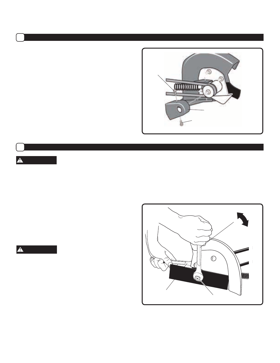
3. Remove the blade locknut that holds the blade to the
drive shaft. (See Figure 11)
To remove or tighten the blade locknut, always use the
method shown in Figure 11. Always position the holding
wrench on the nut behind the blade.
4. Remove the blade.
5. Replace with new blade from the manufacturer by
reversing the above steps.
Note:
Tighten the blade locknut to 35-45 foot-pounds
(47-61 N-m)
3. Remove the two Front Guard Screws and the Belt Guard.
(See Figure 10)
4. Push the blade arm toward the unit to compress the
blade arm spring and slacken the belt. TIP: This can be
accomplished by using a ratcheting tie-down strap.
Always follow the strap manufacturer’s instructions.
5. Remove the old belt from the engine and quill assembly
pulleys.
6. To install a replacement belt from the manufacturer,
reverse the steps above.
• The rear guard bolts should be tightened to 13-16
foot-pounds [18-22N-m].
• The front guard screws should be tightened to 4-6
foot-pounds [6-8N-m].
How to Replace the Belt (Continued)
D
Maintenance
(Continued)
• Save all instructions
13
WARNING
WARNING
Hold Nut,
Do Not Turn
Turn counter-clockwise
to loosen
Blade Locknut
Front Guard
Screws
Belt Guard
Front Guard
Screws
Figure 10
Figure 11
Turn clockwise
to tighten