Introduction, Attaching the cable retainer clip – Patton electronic SmartNode 07MSN4400-QS User Manual
Page 4
Introduction
4
SmartNode 4400 Quick Start Guide
Introduction
This Quick Start Guide leads you through the basic steps to set up a new SmartNode and to download a con-
figuration. Please note that this guide does not replace the detailed SmartWare Software Configuration Guide
and the SmartNode 4400 User Manual available online at
SmartNodes can be used for a wide variety of IP and voice over IP applications. To support and ease the con-
figuration of the SmartNodes configuration templates for the most important applications are available online
at
.
Setting up a new SmartNode consists of the following steps:
1. Attach the power cable retainer clip to the unit
2. Connect a PC to the SmartNode, log in and configure your LAN IP address (see
for details)
3. Connect the SmartNode to the LAN (see
4. Download a configuration example, adapt it to your network, and load it onto the SmartNode (see
)
Airflow requirements – To ensure proper airflow through the SmartNode, follow these recommendations
when you are installing your unit:
– If placed on a desktop, leave 7.62 cm (3 inches) of minimum clearance on both the left and right sides of
the unit.
– If mounted in a rack, leave a one-rack unit (1U) of minimum clearance above and below the unit for
proper airflow.
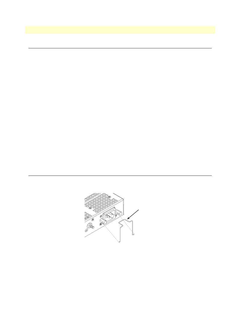
Attaching the cable retainer clip
To secure the power cord, it is necessary to attach the metal retainer clip (if applicable to your model). Squeeze
the clip and insert into the holes in the screws on either side of the power connector on your unit. The clip will
pop into place.
Figure 1. Attaching the cable retainer clip
Note
Refer to the SmartNode 4400 User Manual on the Patton website for
detailed instructions about grounding and connecting power to your
unit.
Power cable
retainer clip