Patton electronic 1140ARC User Manual
Page 11
9
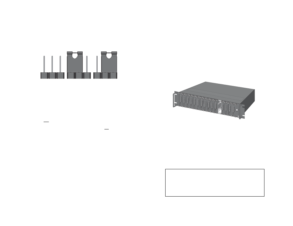
3.2.1 HOW THE JUMPER WORKS
Figure 4 (below) shows the 3-pin jumpers used on the rear card.
The strap enables or disables a particular function depending upon
whether it straddles pins 1 and 2, or pins 2 and 3.
DTE Shield (Pin 1) & FRGND (JB1)
In the connected (closed) position, this strap links DB-25 pin 1 and
frame ground. In the open (disconnected) position, pin 1 is “lifted” from
frame ground.
JB1
Position 1&2 = DTE Shield (Pin 1) and FRGND connected
Position 2&3 = DTE Shield (Pin 1) and FRGND not connected
Figure 4. Orientation of interface card strap
1
2
3
1
2
3
1
2
3
10
4.0 INSTALLATION
This section describes the functions of the Model 1000R16 rack
chassis, tells how to install front and rear Model 1140ARC cards into
the chassis, and provides instructions for connecting the interface
cables.
4.1 THE MODEL 1000R16 RACK CHASSIS
The 1000R16 Rack Chassis (Figure 5, below) has sixteen short
range modem card slots, plus its own power supply. Measuring only
3.5” high, the 1000R16 is designed to occupy only 2U in a 19” rack.
Sturdy front handles allow the 1000R16 to be extracted and transported
conveniently.
4.1.1 THE RACK POWER SUPPLY
The power supply included in the Model 1000R16 rack uses the
same mid-plane architecture as the modem cards. The front card of
the power supply slides in from the front, and the rear card slides in
from the rear. They plug into one another in the middle of the rack.
The front card is then secured by thumb screws and the rear card by
conventional metal screws.
Figure 5. Model 1000R16 rack chassis with power supply
WARNING!
There are no user-serviceable parts in the power
supply section of the Model 1140ARC. Voltage setting changes
and fuse replacement should only be performed by qualified
service personnel. Contact Patton Electronics Technical
support at (301) 975-1007, http://www.patton.com, or
[email protected] for more information.