Optional parts, Connector kit for connection with host controller – Panasonic AC Servo MINAS E Series IMC80A User Manual
Page 34
188
Optional Parts
Connector Kit for Connection with Host Controller
(1) Part No. DV0P0770
(2) Components
(3) Pin arrangement of connector X5 (pin 26) (viewed from the soldering side of the connector)
14
GND
16
OA–
18
OB–
20
OZ–
22
PULS1
24
SIGN1
26
FG
15
OA+
17
OB+
19
OZ+
21
CZ
23
PULS2
25
SIGN2
1
COM+
3
A-CLR
7
CWL
9
ALM
11
BRK-
OFF
13
COM–
2
SRV-
ON
4
CL
8
CCWL
10
COIN
12
WARN
6
DIV
INTSPD1
INTSPD2
5
GAIN
ZEROSPD
1. When wiring, also check pin Nos. carved on the main body of the connector.
2. For codes representative of signal names in the above table or functions of signals, refer to Wiring to
Connector CN X5 (Page 30, 67 and 105).
Name
Connector
Connector Cover
Manufacturer’s part No.
10126-3000PE
10326-52A0-008
Number
1
1
Manufacturer
Sumitomo 3M Ltd
Remarks
For CN X5
(Pin 26)
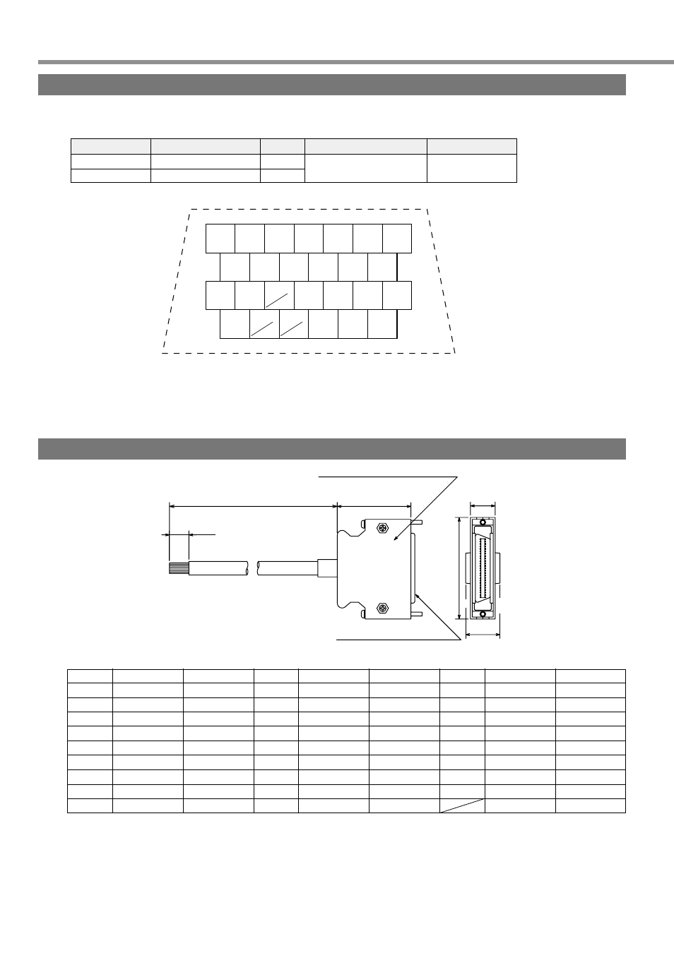
Interface Cable for Connection with Host Controller
(1) Part No. DV0P0800
(2) Outline dimension
(3) Table of Wiring
11
3
26
14
37.2
2000
50
39
Shell Kit : 10326-52AO-008
Sumitomo 3M Ltd or item equivalent to it
Plug : 10126-3000PE
12.7
14
Sumitomo 3M Ltd or item equivalent to it
Pin No.
1
2
3
4
5
6
7
8
9
Color of Core Wire
Orange (red 1)
Orange (black 1)
Gray (red 1)
Gray (black 1 )
White (red 1)
White (black 1)
Yellow (red 1)
Yellow (black 1 )
Pink (red 1)
Signal Name
COM+
SRV-ON
A-CLR
CL/INTSPD2
GAIN/ZEROSPD
DIV/INTSPD1
CWL
CCWL
ALM
Pin No.
10
11
12
13
14
15
16
17
18
Color of Core Wire
Pink (black 1)
Orange (red 2)
Orange (black 2 )
Gray (red 2)
Gray (black 2)
White (red 2)
White (black 2)
Yellow (red 2)
Yellow (black 2)
Signal Name
COIN
BRK-OFF
WARN
COM-
GND
OA+
OA-
OB+
OB-
Pin No.
19
20
21
22
23
24
25
26
Color of Core Wire
Pink (red 2)
Pink (black 2)
Orange (red 3)
Gray (red 3)
Gray (black 3)
White (red 3)
White (black 3)
Orange (black 3)
Signal Name
OZ+
OZ-
CZ
PLUS1
PLUS2
SIGN1
SIGN2
FG
• For example, the color of the wire, Orange (Red 1) means that the lead wire is colored in orange with one red dot
mark.
• The shield of this cable is not connected with the terminal of the connector.
Please use the connector kit for connection with Host Controller when you connect the shield with FG or GND on
the driver side.