Model 3p-mf9 db-9 interface signal/pin# signal/pin – Patton electronic 3P-MF9 User Manual
Page 8
7
APPENDIX B
PATTON MODEL 3P-MF & 3P-MF9 PIN ASSIGNMENTS
* Note Model 3P-MF applies power to pin 9 (DCV+) only. All other sig-
nals are passed through unmodiÞed from end-to-end. Signal
names are provided here to more closely represent the EIA-232
standard (see Appendix C on page 8).
* Note Model 3P-MF9 applies power to pin 9 (DCV+) only. All other sig-
nals are passed through unmodiÞed from end-to-end. Signal
names are provided here to more closely represent the EIA-232
standard (see Appendix C on page 8).
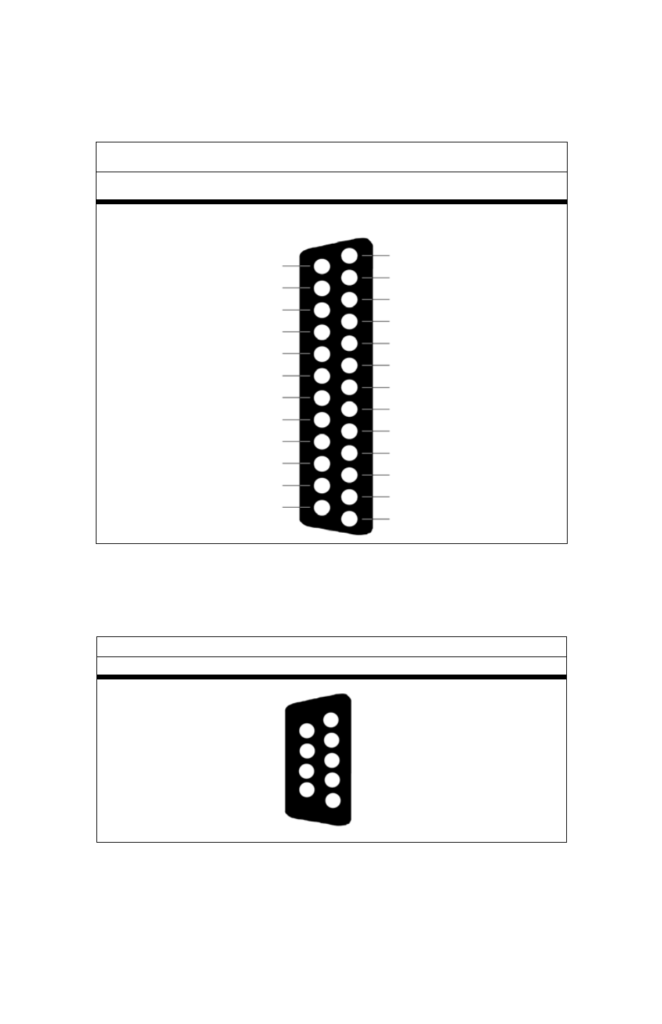
Model 3P-MF DB-25 Interface
SIGNAL/PIN#
SIGNAL/PIN#
Secondary Transmit Data - 14
Transmit Clock - 15
Secondary Receive Clock - 16
Receiver Clock - 17
Local Loopback - 18
Secondary Request to Send - 19
Data Terminal Ready - 20
Remote Loopback - 21
Ring Indicator - 22
Data Signal Rate Selector - 23
Transmit Clock - 24
Test Mode - 25
1 - (FG) Frame Ground
2 - (TD) Transmit Data
3 - (RD) Receive Data
4 - (RTS) Request to Send
5 - (CTS) Clear to Send
6 - (DSR) Data Set Ready
7 - (SG) Signal Ground
8 - (CD) Carrier Detect
9 - (DCV+) DC Test Voltage*
10 - (DCV-) DC Test Voltage
11 - Unassigned
12 - Secondary Rcvd Line
13 - Secondary Clear to Send
Model 3P-MF9 DB-9 Interface
SIGNAL/PIN#
SIGNAL/PIN#
Data Set Ready (DSR) - 6
Ready to Send (RTS) - 7
Clear to Send (CTS) - 8
*DC Test Voltage (DCV+)- 9
1- (CD) Carrier Detect
2 - (RD) Receive Data
3 - (TD) Transmit Data
4- (DTR) Data Terminal Ready
5- (SG/FG) Signal Ground/ Frame Ground