Peavey S-14 User Manual
Page 11
11
31
32
33
34
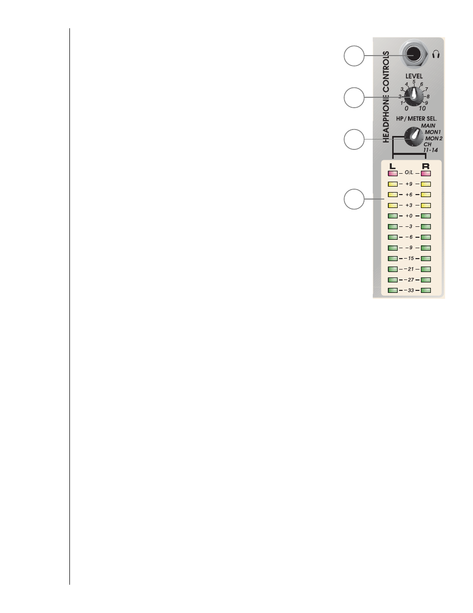
31. HEADPHONE OUTPUT: This stereo jack (TRS) provides drive for
the headphones. The level is set by the headphone level control.
Tip = Left, Ring = Right, Shield = Ground.
32. HEADPHONE LEVEL: This control sets the volume of the
headphones.
33. HEADPHONE/METER SOURCE: Selects the signal(s) sent to the
headphone amplifier and to the output meter array. Options include
the main L/R outputs, monitor1, monitor2, or a cue mix of channel
11/12 and 13/14 pre-fader signals. This last position is useful for setting
up tapes and CDs (on channels 11/12 and 13/14). Muting the stereo
channels during cueing does not affect the headphone signal but
prevents the audio from being sent to the speaker systems.
34. LED METER ARRAY: A 12 segment peak reading LED array monitors
the level of the signals selected by the Headphone Source switch.
When the switch is in the MAIN position, the meters monitor the left
and right outputs. The 0dB reference level corresponds to +4dBu. In
normal operation, the channel gains should be set so that the meters
light near 0dB at loud points in the service. The output trim attenuator
on the rear panel should then be adjusted for the desired house
volume. This will give the best signal to noise ratio. The same
procedure should be used on the monitor outputs, but the power
amplifier input controls will need to be set for desired volume. Setting
the output trim is part of the S-14 setup procedure.