Troubleshooting, Maintenance – Porter-Cable 314 User Manual
Page 2
NEvER cut ferrous metals (those with any iron or steel content), masonry, glass or tile with
this saw. Damage to the saw and personal injury may result.
A dull blade will cause inefficient cutting, overload on the saw motor, excessive splintering and increase
the possibility of kickback. Change blades when it is no longer easy to push the saw through the cut,
when the motor is straining, or when excessive heat is built up in the blade. It is a good practice to keep
extra blades on hand so that sharp blades are available for immediate use. Dull blades can be sharp-
ened in most areas; see SAWS-SHARPENING in the yellow pages. Hardened gum on the blade can be
removed with kerosene, turpentine, or oven cleaner. Anti-stick coated blades can be used in applications
where excessive build-up is encountered, such as pressure treated and green lumber.
LOWER BLADE GUARD
The lower blade guard is a safety feature which reduces the risk of serious personal injury.
Never use the saw if the lower guard is missing, damaged, misassembled or not working properly. Do
not rely on the lower blade guard to protect you under all circumstances. Your safety depends on follow-
ing all warnings and precautions as well as proper operation of the saw. Check lower guard for proper
closing before each use as outlined in Additional Safety Rules for Circular Saws. If the lower blade guard
is missing or not working properly, have the saw serviced before using. To assure product safety and
reliability, repair, maintenance and adjustment should be performed by an authorized PORTER-CABLE
service center or other qualified service organization, always using identical replacement parts.
TO ADJUST DEPTh-OF-cUT FOR NORMAL cUTTING
To reduce the risk of injury, turn unit off and disconnect it from power source before
installing and removing accessories, before adjusting or when making repairs. An accidental start-
up can cause injury.
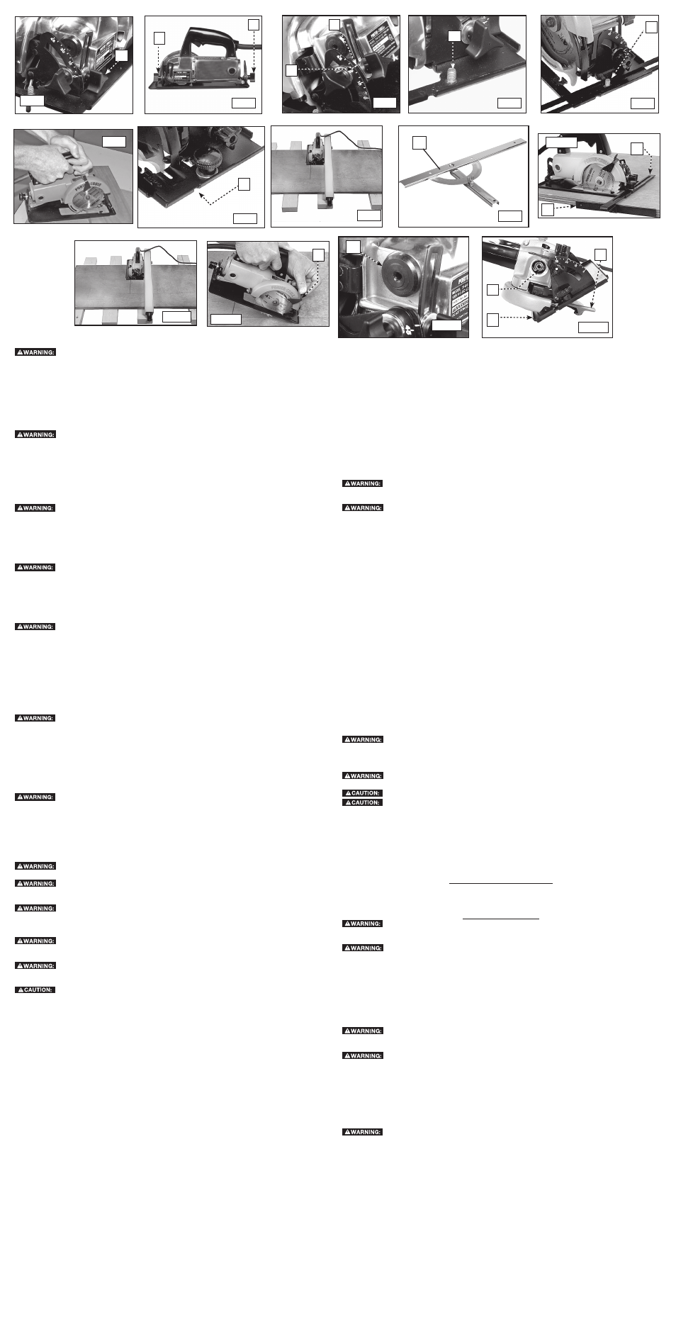
Loosen the depth-adjusting knob (A) Fig. 1, and raise or lower the saw housing until the blade extends
the desired distance below the base. For best results, the blade should barely protrude through the
workpiece. Firmly tighten the knob to hold the saw in position.
TO ADJUST FOR BEvEL cUTS
To reduce the risk of injury, turn unit off and disconnect it from power source before
installing and removing accessories, before adjusting or when making repairs. An accidental start-
up can cause injury.
Loosen the front (A) Fig. 2 and rear (B) Fig. 2 angle-adjusting knobs. Tilt the saw housing until the
desired graduation mark (C) Fig. 3 lines up with the indicating line (D) Fig. 3 on the depth-adjusting
bracket. Firmly tighten the knobs to hold the saw in the selected position.
TO ATTAch ThE BASE INSERT
To reduce the risk of injury, turn unit off and disconnect it from power source before
installing and removing accessories, before adjusting or when making repairs. An accidental start-
up can cause injury.
The base insert is used to reduce chipping and splintering of the top fibers of plywood and paneling
when used in conjunction with a fine tooth blade. When the base insert is used. You can cut either side
(finished or unfinished) of the workpiece.
NOTE: Do not use this insert when making bevel cuts.
Adjust the saw for the minimum depth-of-cut. Place the slot of the insert around the stud (A) Fig. 4 on
the front of the saw base. Install a flat washer and thumb nut to the stud loosely. Adjust the saw for
the desired depth of cut, and align the insert so that the saw blade is centered in the slot in the insert.
Tighten the thumb nut firmly.
LINE-OF-cUT INDIcATOR
To reduce the risk of injury, turn unit off and disconnect it from power source before
installing and removing accessories, before adjusting or when making repairs. An accidental start-
up can cause injury.
A notch is provided on the front edge of the base to assist in following the line of cut marked on the
workpiece.
The left edge of the notch (A) Fig. 7 is marked "45". Use this edge to follow the line when making 45º
bevel cuts. The right edge of the notch is marked "0". Use this edge to follow the line when making 90º
cuts.
INSTALLING ThE OPTIONAL RIP GUIDE
To reduce the risk of injury, turn unit off and disconnect it from power source before
installing and removing accessories, before adjusting or when making repairs. An accidental start-
up can cause injury.
Adjust the saw for the minimum depth-of-cut. Place the slot in the rip guide over the stud (A) Fig. 5 on
the front of the saw base.
Install a flat washer and thumb nut on the stud loosely. Adjust the guide to the desired width-of-cut.
Take into consideration the blade thickness and set. Tighten the thumb nut firmly.
hOW TO USE ThE SAW
If the guard binds or is sluggish, return the saw to your nearest authorized Porter-Cable
service center for repair.
For maximum protection, effective control of this powerful saw requires two-handed
operation. support the work properly and hold the saw firmly to prevent loss of control which could cause
injury. Refer to Figure 6 for the proper way to hold the saw.
Stay alert and maintain a firm grip on the saw. Release the switch immediately if the
blade binds or the saw stalls. Keep your blade sharp. Properly support panels (Fig. 11). Use a fence or a
straight edge guide when ripping. DO NOT force the tool. DO NOT remove the saw from the workpiece
while the blade is moving.
To help reduce the risk of personal injury, always clamp work. Don’t try to hold short
pieces by hand! Remember to support cantilevered and over hanging material. Use caution when saw-
ing material from below.
Be sure that the saw is up to full speed before blade contacts material to be cut. Starting
the saw with blade against material to be cut or pushed forward into kerf can result in kickback and
personal injury.
Do not operate your tool on a current on which the voltage is not within correct limits. Do
not operate tools rated AC only on DC current. To do so may seriously damage the tool.
KIcKBAcK
When the saw blade becomes pinched or twisted in the cut, kickback can occur. The saw is thrust
rapidly back toward the operator. When the blade is pinched or bound tightly by the kerf closing
down, the blade stalls and the motor reaction drives the unit backward. When the blade becomes
twisted or misaligned in the cut, the teeth at the back edge of the blade can dig into the top sur-
face of the wood causing the blade to climb out of the kerf and jump back toward the operator.
Kickback is more likely to occur when any of the following conditions exist.
1.
IMPROPER WORKPIEcE SUPPORT
A. Sagging or improper lifting of the cut off piece can cause pinching of the blade and lead to kick-
back.
B. Cutting through material supported at the outer ends only can cause kickback. As the material
weakens it sags, closing down the kerf and pinching the blade.
C. Cutting off a cantilevered or overhanging piece of material from the bottom up in a vertical direc-
tion can cause kickback. The falling cut off piece can pinch the blade.
D. Cutting off long narrow strips (as in ripping) can cause kickback. The cut off strip can sag or twist
closing the kerf and pinching the blade.
E. Snagging the lower guard on a surface below the material being cut momentarily reduces opera-
tor control. The saw can lift partially out of the cut increasing the chance of blade twist.
2.
IMPROPER DEPTh OF cUT SETTING ON SAW
To make the most efficient cut, the blade should protrude only far enough to expose 1/2 of a tooth.
This allows the shoe to support the blade and minimizes twisting and pinching in the material. See
the section titled “Cutting Depth Adjustment.”
3.
BLADE TWISTING (MISALIGNMENT IN cUT)
A. Pushing harder to cut through a knot, a nail, or a hard grain area can cause the blade to twist.
B. Trying to turn the saw in the cut (trying to get back on the marked line) can cause blade twist
C. Over-reaching or operating the saw with poor body control (out of balance), can result in twisting
the blade.
D. Changing hand grip or body position while cutting can result in blade twist.
E. Backing up the saw to clear blade can lead to twist if it is not done carefully.
4
MATERIALS ThAT REQUIRE EXTRA ATTENTION
A. Wet lumber
B. Green lumber (material freshly cut or not kiln dried)
C. Pressure treated lumber (material treated with preservatives or anti-rot chemicals)
5.
USE OF DULL OR DIRTY BLADES
Dull blades cause increased loading of the saw. To compensate, an operator will usually push
harder which further loads the unit and promotes twisting of the blade in the kerf. Worn blades
may also have insufficient body clearance which increases the chance of binding and increased
loading.
6.
LIFTING ThE SAW WhEN MAKING BEvEL cUT
Bevel cuts require special operator attention to proper cutting techniques - especially guidance
of the saw. Both blade angle to the shoe and greater blade surface in the material increase the
chance for binding and misalignment (twist) to occur.
7.
RESTARTING A cUT WITh ThE BLADE TEETh JAMMED AGAINST ThE MATERIAL
The saw should be brought up to full operating speed before starting a cut or restarting a cut
after the unit has been stopped with the blade in the kerf. Failure to do so can cause stalling and
kickback.
Any other conditions which could result in pinching, binding, twisting, or misalignment of the blade
could cause kickback. Refer to the sections on “Adjustments And Set-Up” and “Operation” for pro-
cedures and techniques that will minimize the occurrence of kickback.
cROSScUTTING AND BEvEL cUTS
To reduce the risk of injury, turn unit off and disconnect it from power source
before installing and removing accessories, before adjusting or when making repairs. An
accidental start-up can cause injury.
Use the lever (A) Fig. 12 provided on the lower blade guard when you have to
retract the lower blade guard manually.
Support the workpiece on a firm bench, saw horse, or other rigid support and securely hold it in
place. Extend the end to be cut off beyond and to the right of the support. Clear the area beneath
the line of cut of all objects that would interfere with the blade protruding through the workpiece.
Place the front edge of the saw base squarely on the work and keep the tip of the saw blade clear
of the work. Depress the switch trigger and allow the saw motor to reach full speed. Maintain the
relationship of the notch in the front edge of the base with a marked line on the workpiece. Advance
the saw steadily through the workpiece. Do not force the saw through the workpiece. At the
completion of the cut, release the switch trigger.
Bevel cuts are made in the same manner as cross-cuts, except that the saw base is tilted to the
desired angle. An optional protractor gauge (A) Fig. 9 is available to aid in cutting compound angles.
This gauge is also useful for crosscutting operations.
RIPPING
Ripping is cutting wood lengthwise. This operation is performed the same as crosscutting with
the exception of supporting the workpiece. If the workpiece is supported on a large table, bench,
or floor, several pieces of scrap stock approximately one inch thick should be placed beneath the
workpiece to allow clearance for the protruding section of the blade. Large sheets of paneling or
thin plywood supported on saw horses should have 2 x 4’s placed lengthwise between the horses
and the workpiece to prevent it from sagging.
For narrow rip cuts, use the rip guide (A) Fig. 10 (available as an accessory). Guide the saw by
keeping the inner face of the rip guide (B) tight against the edge of the board.
PANEL cUTS
For making wide cuts (plywood, paneling, etc.), use a wooden guide strip. Clamp or tack this strip
to the workpiece far enough back from the line-of-cut to act as a fence for the left edge of the saw
base (Fig. 11). The location of this strip will have to allow for the distance from the left side of the
base to the blade so that the blade will cut exactly where desired. This strip should extend beyond
each end of the workpiece.
Support the material being cut with 2 x 4’s or scrap material to provide blade clearance
beneath the material and to provide a firm work surface.
POcKET cUTS (PLUNGE cUTTING)
Use the lever (A) Fig. 12 provided on the lower guard when you have to retract the
guard manually.
Keep your hands and fingers away from the blade.
Let the saw come to a complete stop before removing it from the workpiece.
A pocket cut starts inside the workpiece and not from the edge. Mark the area clearly with lines on
all sides. Start near the corner of one side and place the front edge of the saw base firmly on the
workpiece. Hold the saw up so that the blade clears the workpiece. Adjust the blade properly for the
depth-of-cut. For best results, adjust the blade so that it barely protrudes through the workpiece.
Push the lower blade guard lever all the way forward so that the blade is exposed (Fig. 12). Be very
careful not to contact the blade. Start the motor and lower the blade into the work. After the blade
has cut through and the base rests flat on the work, follow your marked line to the corner. Use a
keyhole or bayonet saw to cut the corners.
TROUBLEShOOTING
For assistance with your tool, visit our website at www.deltaportercable.com for a list of service centers,
or call the Porter-Cable Customer Care Center at (888) 848-5175.
MAINTENANcE
To reduce the risk of injury, turn unit off and disconnect it from power source
before installing and removing accessories, before adjusting or when making repairs. An
accidental start-up can cause injury.
ALWAYS USE SAFETY GLASSES. Everyday eyeglasses are NOT safety glasses. Also
use face or dust mask if cutting operation is dusty. ALWAYS wear certified safety equipment:
• ANSI Z87.1 eye protection (CAN/CSA Z94.3)
• ANSI S12.6 (S3.19) hearing protection
• NIOSH/OSHA respiratory protection.
REPAIRS
For assistance with your tool, visit our website at www.deltaportercable.com for a list of service centers,
or call the Porter-Cable Customer Care Center at (888) 848-5175.
cLEANING
Periodically blowing dust and chips out of the motor housing using clean, dry com-
pressed air is a suggested maintenance procedure. To reduce the risk of serious personal injury,
ALWAYS wear ANSI Z87.1 safety glasses while using compressed air.
When cleaning, use only mild soap and a damp cloth on plastic parts. Many house-
hold cleaners contain chemicals which could seriously damage plastic. Also, do not use gasoline,
turpentine, lacquer or paint thinner, dry cleaning fluids or similar products which may seriously dam-
age plastic parts. NEVER let any liquid get inside the tool; NEVER immerse any part of the tool into
a liquid.
FAILURE TO START
Should your tool fail to start, check to make sure the prongs on the cord plug are making good contact
in the outlet. Also, check for blown fuses or open circuit breakers in the line.
LUBRIcATION
To reduce the risk of injury, turn unit off and disconnect it from power source
before installing and removing accessories, before adjusting or when making repairs. An
accidental start-up can cause injury.
Although all Porter-Cable tools have been thoroughly lubricated with a sufficient amount of high
grade lubricant at the time of manufacture, check the oil level in the gear chamber before using your
saw and periodically thereafter. To check the oil level:
1. Remove the saw blade to prevent accidental contact when checking the oil level.
2. Adjust the saw for the maximum depth-of-cut and 45
º bevel cut. Firmly tighten all knobs.
3. Connect the power to the tool. Turn the saw
"ON" and run it for approximately two minutes.
4. Loosen the oil plug (A) Fig. 13 with the provided wrench.
5. Remove the oil plug and seal. Set the saw on a level surface so that it rests on points (A) and
(B) Fig. 14.
6. Gear lubricant should be level with the bottom of the hole (C) but should not run out. If the level
is low, add a small amount of lubricant (90 weight gear oil, furnished with your saw) until it is
even with the bottom of the hole.
7.
NOTE: DO NOT OvERFILL. The pressure created by the pumping action of the gears could
force the lubricant through the seals and into the motor chamber, causing damage to the
motor.
8. Install the oil plug and gasket.
9. Replace the saw blade.
A
Fig. 1
Fig. 2
Fig. 3
A
B
D
c
Fig. 4
Fig. 5
A
A
Fig. 7
A
Fig. 8
Fig. 9
Fig. 6
Fig. 10
B
Fig. 11
Fig. 12
Fig. 13
Fig. 14
A
B
c
A
A
A
A