Patton electronic RS-232 User Manual
Page 4
SWITCH SET SW1
The configuration switches on switch set SW1 set analog
loopback, digital loopback and V.54 enable/disable. The default
settings are summarized in Figure 3 (below).
SW1-1: DTE Initiation of Local Analog Loopback Test
The setting for switch SW1-1 determines whether or not the Model
1035’s local analog loopback test can be initiated by raising pin 18 on
the DTE.
SW1-1
Setting
On
Pin 18 initiation enabled
Off
Pin 18 initiation disabled
SW1-2: DTE Initiation of Remote Digital Loopback Test
The setting for switch SW1-2 determines whether or not the Model
1035’s remote digital test can be initiated by raising pin 21 on the DTE.
SW1-2
Setting
On
Pin 21 initiation enabled
Off
Pin 21 initiation disabled
SW1-3 through SW1-7: Not Used
(continued)
5
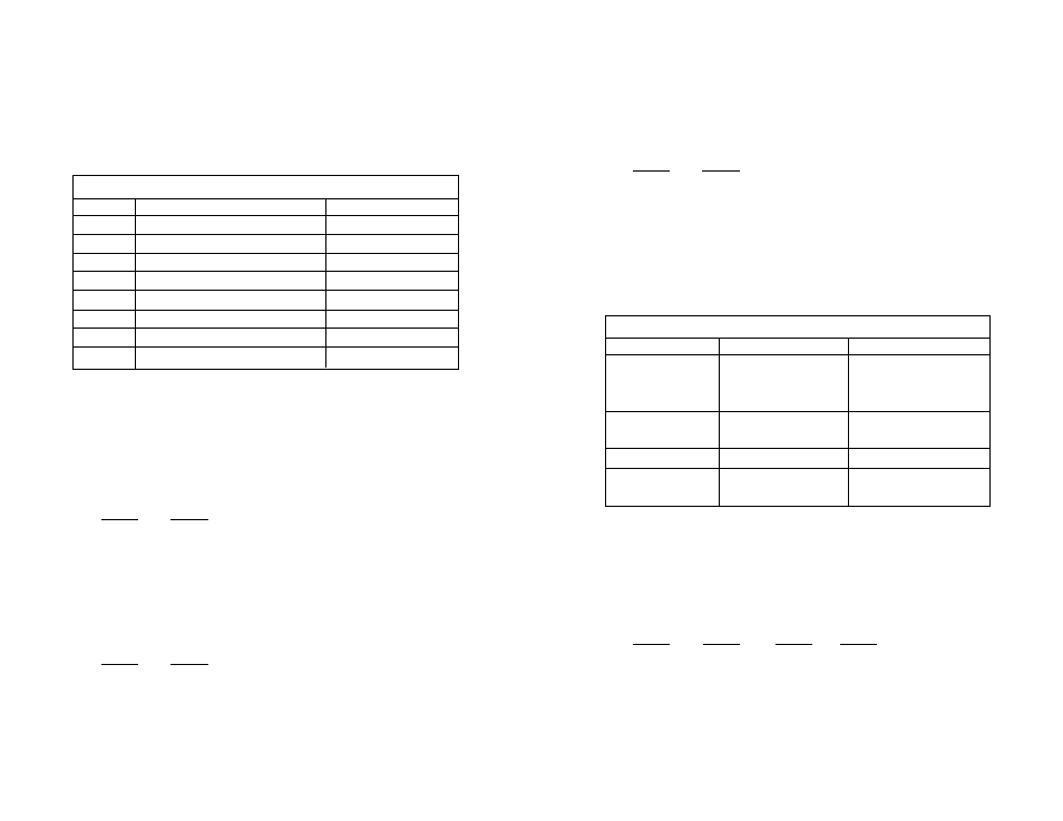
SW1 SUMMARY TABLE
Position
Function
Factory Default
SW1-1
DTE Control of Analog Loopback
On
Enabled
SW1-2
DTE Control of Digital Loopback
On
Enabled
SW1-3
Not Used
Off
n/a
SW1-4
Not Used
Off
n/a
SW1-5
Not Used
Off
n/a
SW1-6
Not Used
Off
n/a
SW1-7
Not Used
Off
n/a
SW1-8
V.54 Enable/Disable
Off
Enabled
Figure 3. Summary of DIP switch settings for set SW1
SW1-8: V.54 Enable/Disable
The setting for switch SW1-8 determines whether or not the Model
1035’s V.54 circuits are enabled.
SW1-8
Setting
On
V.54 test functions disabled
Off
V.54 test functions enabled
SWITCH SET SW2
The configuration switches on switch set SW2 set data rate, clock
source, carrier control and RTS/CTS delay. The default settings are
summarized in Figure 4.
SW2-1 through SW2-3: Data Rate Setting
Switches SW2-1 through SW2-3 are set in combination to
determine the synchronous data rate for the Model 1035.
SW2-1
SW2-2
SW2-3
Setting
On
Off
Off
64 Kbps
Off
On
Off
56 Kbps
Off
Off
On
32 Kbps
(continued)
6
SW2 SUMMARY TABLE
Position
Function
Factory Default
SW2-1
Data Rate
Off
SW2-2
Data Rate
On
SW2-3
Data Rate
Off
SW2-4
Clock Source
On
SW2-5
Clock Source
On
SW2-6
Carrier Control
Off
Constantly On
SW2-7
RTS/CTS Delay
On
SW2-8
RTS/CTS Delay
On
Internal
56 Kbps
Figure 4. Summary of DIP switch settings for set SW2
}
}
7 ms
}