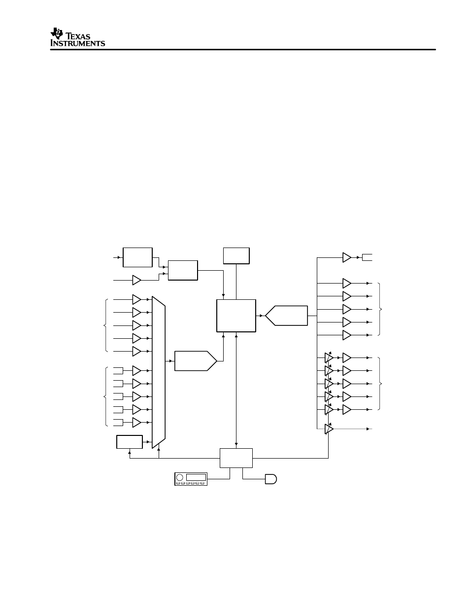
Figure 1. digital surround receiver block diagram – Philips TMS320C6713 User Manual
Page 3
SPRA921
3
TMS320C6713 Digital Signal Processor Optimized for High Performance Multichannel Audio Systems
•
Glueless external memory interface (EMIF) capable of interfacing to SDRAM for bulk
external storage of additional code or delay buffers. The EMIF also supports synchronous
burst SRAM (SBSRAM), asynchronous memories, and peripherals with parallel interfaces.
•
A host-port interface (HPI) for direct connection to a host processor
Figure 3 shows additional peripherals and the internal connection of the device. This includes:
•
A highly efficient 16-channel enhanced direct memory access (EDMA) controller connects
the peripherals to the internal and external memory. This controller can interleave transfers
from different sources/destinations on a cycle-by-cycle basis, avoiding dead time of most
DMAs when a higher priority transfer interrupts a lower priority one.
•
Highly configurable PLL and clocking control logic to enable a variety of ratios of system and
CPU clocks
•
256K bytes of internal memory to provide a large internal program and data store
•
Two multichannel buffered serial ports (McBSPs) provide general connection to multiple
serial standards including SPI
•
Two general-purpose timers to count system events or generate clock outputs
Optical
digital
receiver
Optical
digital
in
in
digital
Coaxial
S/P DIF
receiver
L
R
R
L
R
L
R
L
R
L
Stereo
analog
in
analog
Multichannel
in
TMS320C6713
Multichannel
A to D
conversion
RAM/ROM
conversion
D to A
Multichannel
Tuner
System
controller
User displays
and controls
IR receiver
L
R
Amp
Amp
Amp
Amp
Amp
Record out
Multichannel
analog
out
Speaker
level
out
Subwoofer
out
Multiplexer
Figure 1. Digital Surround Receiver Block Diagram