Adat-4 internal jumpers, Adat-4 user guide page 7 – Philips ADAT-4 User Manual
Page 13
ADAT-4 User Guide
Page 7
ADAT-4 Internal Jumpers
This section provides information about the ADAT-4’s internal jumpers and switches.
NOTE For detailed instructions on opening and closing the ADAT-4, see “Inside the
Module.”
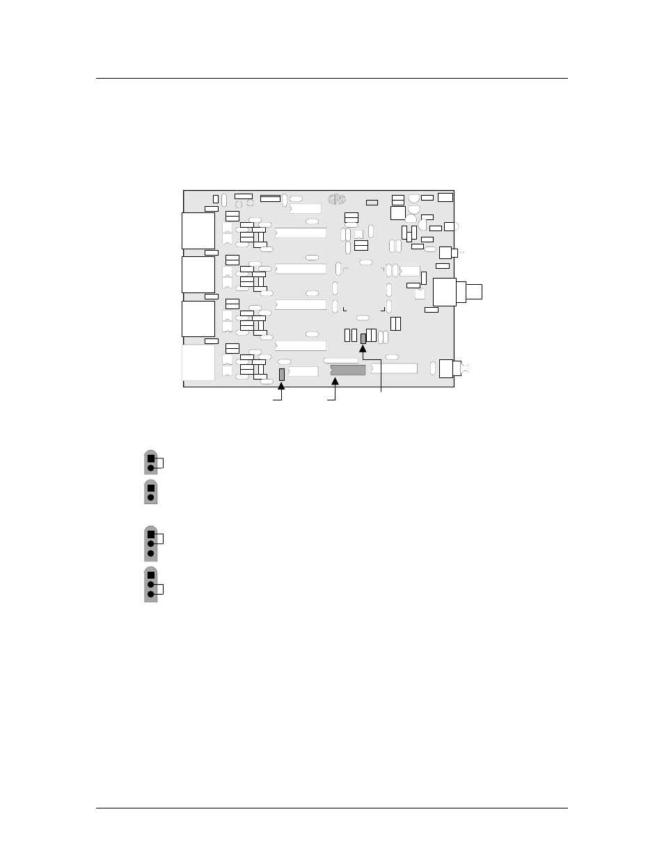
The figure below shows the ADAT-4’s internal jumper locations:
20/24 Bit
Jumper
Word Clock
Polarity Jumper
ADAT-4
04-0236-
G
R
AHAM
-PAT
T
E
N SYST
EM
S
G
R
ASS VAL
L
EY,
CAL
IF
O
RNI
A
Made in U.S
.A
.
J5
SW2
J2
Status
Dip Switch
• J2 is the 20/24 Bit jumper.
1
2
– To set all 4 channels to 24 bits, install the jumper. This is the default
configuration.
1
2
– To set all 4 channels to 20 bits, remove the jumper. In 20-bit mode, any
auxiliary data on the AES inputs will be discarded.
• J5 is the Word Clock Input Polarity jumper.
1
2
3
– To leave work clock input reference normal, strap the jumper between pins
1 and 2. The rising edge is used as reference.
1
2
3
– To invert the work clock input reference, strap the jumper between pins 2
and 3. The falling edge is used as reference.