6 cabinet-to-bracket attachment, 7 connecting the ac transformer, 8 powermax-compatible detectors – PowerMax DE5450 User Manual
Page 6
6
DE5450
You will need the following telephone-type cords:
• For telephone line hookup only (installations where
line seizure is not required): 6-lead RJ-11 cord(s).
• For telephone line-and-set hookup (typical installation
requiring line seizure): 8-lead RJ-31X cord(s).
Note: RJ-11 and RJ-31X cords are available as either
single ended with flying leads at the other end, or
double-ended. Use a double-ended cord if the telephone
line jack is located near the panel. If the telephone line
jack is far away, use two single ended cords and splice
them together with 4-conductor cable.
• For X-10 connection: 6-lead RJ-11 double-ended cord.
Only 4 leads are used - make sure the cord is “1 to 1”.
Refer to Figure 10 and proceed as follows:
A. Use the cords to complete the following connections:
"
The LINE socket to the telephone line (or the LINE &
SET socket to the telephone line and the local
telephone set).
"
The X-10 socket to the powerline interface module.
B. Extract the screw terminal blocks one by one and make
the necessary connections. When done, plug each
terminal block onto its PCB mounted pins.
IMPORTANT! The terminals for internal and external
sounders are DC outputs intended for 9V sounders.
Connecting a loudspeaker to any of these outputs
will cause a short circuit and will damage the unit.
C. Route the wires and cords via the rear wiring channels.
With all wires properly seated, proceed to Para. 3.6.
3.6 Cabinet-to-Bracket Attachment
Once all connections are made and the wires are seated
within the channels at the rear, it is only necessary to
attach the control panel to the wall-mounted bracket.
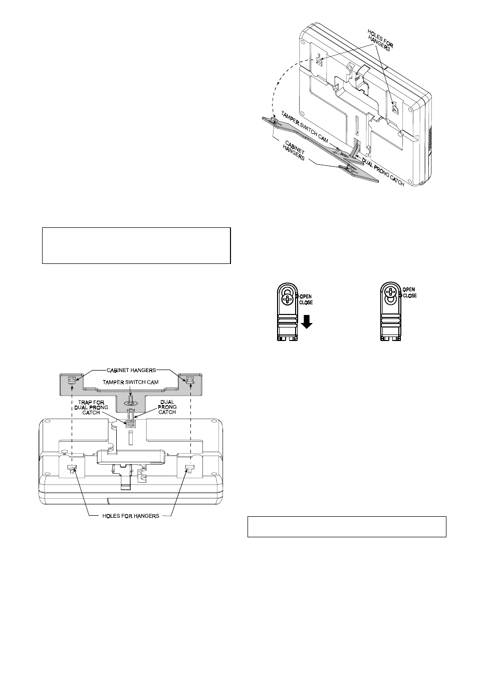
Refer to Figure 11 and proceed as follows:
A. Hold the cabinet with its top slightly slanted toward
yourself and align the trap at the bottom of the cabinet
with the dual-prong catch at the bottom of the bracket.
Figure 11. Cabinet-to-Bracket Assembly - Top View
B. Allow the dual prong catch to enter the trap as far as it
will go while slanting the cabinet towards your stomach.
C. Using the dual prong catch as a pivot, bring the top of
the cabinet closer to the wall, allowing the two hangers
to enter the two corresponding holes in the cabinet.
D. Once the cabinet is flush against the bracket, slide it
down as far as the hangers will allow (about 10 mm).
The dual prong catch at the bottom should snap into
place with a click.
Figure 12. Cabinet-to-Bracket Assembly - Side View
E . Pry the left side cover loose and remove it as explained
in Para. 3.2, Steps A through C.
F . You will find the bracket locking device in the open
position shown in Figure 13, part A.
G . Make sure that the screw is loose enough to allow
shifting the lock down.
H . Shift the lock down as shown by the arrow to reach the
position viewed in part B and tighten the screw.
A. OPEN
B. CLOSED
Figure 13. Locking the Bracket
I. Test the assembly by lightly pulling the cabinet away
from the wall. If correctly mounted, the cabinet will
adhere to the bracket.
Note: See Para. 5.1 for dismounting procedure.
3.7 Connecting the AC Transformer
CAUTION! Do not plug the transformer into the AC
outlet before completing all other wiring.
A. U.S.A. only: Remove the center screw from the AC
wall outlet.
B. Plug the transformer directly in - the Power LED of the
control panel should illuminate.
C. U.S.A. only: Use the screw removed in Step A above
to secure the transformer to the AC outlet. Tighten the
screw well.
D. The distance of the transformer from the system should
not exceed 150 ft using 18 AWG conductors.
For UL installations, do not connect to a receptacle
controlled by a switch.
3.8 PowerMax-Compatible Detectors
Each detector compatible with the PowerMax system is
packed with its own installation instructions. Read them
carefully and install as indicated.
A. PIR Motion Detectors
The wireless passive infrared (PIR) motion detectors used
in the system are of the PowerCode type. The PowerMax