3 programming, 4 mounting the bracket – PowerMax DE5450 User Manual
Page 4
4
DE5450
D . Remove the screw that secures the lid (see Figure 3),
swing the lid up and pull it away. You now have access
to the battery holder (see Figure 4).
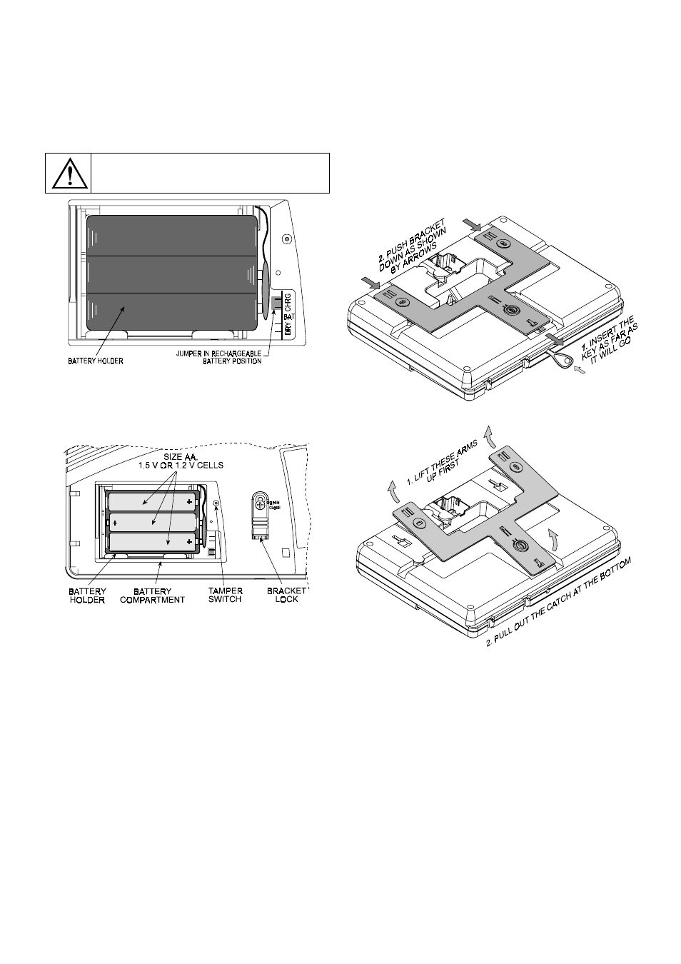
E . Pull out the battery holder and check that the battery
type selection jumper is positioned in accordance with
the type of batteries being installed (see Figure 4). For
alkaline (dry) cells, the jumper should be mounted on
the two lower pins. For Nickel Cadmium (rechargeable)
cells - on the two upper pins.
CAUTION! Verify that the jumper is at the
correct position for the actual battery cells
being installed.
Figure 4. Battery Type Selection Jumper
F. Insert all 6 battery cells - 3 at the top and 3 at the bottom.
Make sure that the flat (–) end of each cell is pressed
against a circular spring and the capped (+) end of each
cell is pressed against a flat contact.
Figure 5. Battery Holder in Place with Batteries Installed
G. Put the battery holder back in, re-mount the battery
compartment lid and re-attach it using the screw.
Disregard any trouble indications that may appear
(due to lack of AC or lack of telephone line connection).
H. Put back the battery area cover - insert the angled legs
at the left edge into their holes and then press the right
edge of the cover against the cabinet surface until the
catches click into place.
3.3 Programming
It pays off to plan ahead - use the tables in appendices A
and B at the end of this guide to register the intended
location of each detector, the holder and assignment of
each transmitter and the control plan for the X-10 units.
Gather up all transmitters and detectors used in the
system and mark each one in accordance with your
deployment plan.
Program the system now as instructed in the PowerMax
programming Guide (Publication DE5450P).
3.4 Mounting the Bracket
A. Detaching the Bracket from the Cabinet
A notable advantage of the PowerMax is that the unit can
be mounted without having to open its cabinet. All
connectors and terminals are accessible through a
rectangular opening at the rear, and wiring channels are
provided across the rear of the cabinet. Quick mounting of
the PowerMax is possible by virtue of a special bracket
and a unique mechanical coupling / locking mechanism.
The control panel comes with the bracket in place at the
rear. The bracket lock at the front (see Figure 5) is left
open. Since a catch at the lower end of the bracket is
trapped within the cabinet, a special plastic key (supplied
in the kit) must be used to release it - see Figures 6 & 7.
Figure 6. Releasing the Bottom Catch from the Trap
Figure 7. Detaching the Bracket
B. Getting Acquainted with the Bracket
Having detached the bracket successfully, put it on a desk
and observe its design - see Figure 8 for identification of
its various parts.
The upper and lower mounting holes are intended for
regular attachment to the wall with screws and anchors.
A special “ring and cam” piece is connected to the bottom
leg of the bracket by 3 breakable plastic joints. A large
plastic washer supplied with the bracket must be inserted
into the ring to allow fastening the ring to the wall. With the
washer in place, a fourth screw can be used to secure the
ring and cam piece to the wall.
Once the control panel is mounted in place, the cam
enters a slot in the control panel’s rear part and maintains
the built in tamper switch pressed. Separating the control